
A kind of superpressure aeration device and its application

An aeration device and high-pressure air chamber technology, applied in fertilization device, application, transportation and packaging, etc., can solve the problems of affecting aeration effect, short residence time, uneven dispersion, etc., to achieve good aeration effect, fog Good chemical effect and good fertilization effect

Active Publication Date: 2022-05-10
梁荷
View PDF21 Cites 0 Cited by
  • Summary
  • Abstract
  • Description
  • Claims
  • Application Information

AI Technical Summary

Problems solved by technology

The bubbles of the large and medium bubble type aeration device are relatively large, the bubbles rise quickly in the liquid, and the residence time is short, so they cannot play the role of oxygen supply well; while the bubbles of the ultra-micro bubble aeration device are small, the pressure is relatively high Low air bubbles are easy to gather and agglomerate in the liquid, and cannot be evenly dispersed in the liquid, thus affecting the aeration effect

Method used


Image

  • A kind of superpressure aeration device and its application
  • A kind of superpressure aeration device and its application

Examples


Embodiment 1

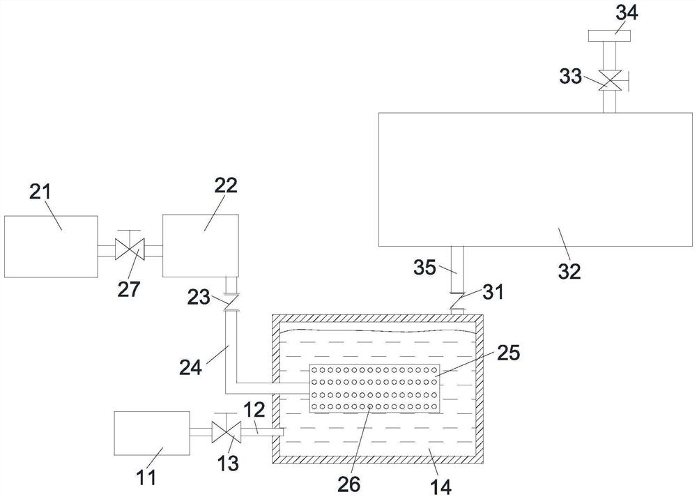
[0027] as attached figure 1 Shown: the present embodiment provides a kind of superpressure aeration device, comprises high-pressure liquid chamber 14, is located at the high-pressure air chamber 25 in the high-pressure liquid chamber 14, and the gas-liquid mixing chamber 32 that conducts with high-pressure liquid chamber 14, and with The nozzle 34 connected to the gas-liquid mixing chamber 32; the high-pressure gas chamber 25 is connected to a gas supply device, and the gas supply device is used to feed pressurized gas into the high-pressure gas chamber 25; the high-pressure liquid chamber 14 is connected to a liquid supply device, the liquid supply device is used to feed pressurized liquid into the high-pressure liquid chamber 14; the surface of the high-pressure gas chamber 25 is provided with a number of air holes 26 for feeding gas into the high-pressure liquid chamber 14; the high-pressure liquid chamber 14 and the gas-liquid mixing chamber 32 is provided with a throttlin...

Embodiment 2

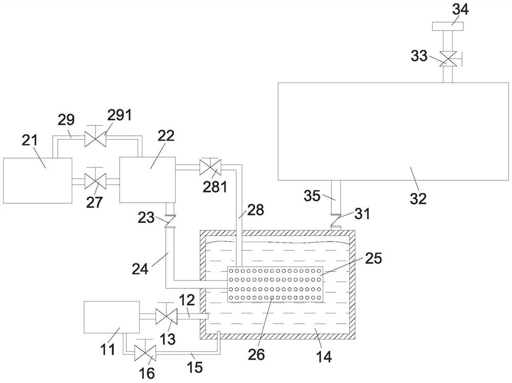
[0039] as attached figure 2 As shown, a first return air pipe 28 is provided between the high-pressure gas chamber 25 and the intermediate pressurized chamber 22 of this embodiment, and a first return air valve 281 is arranged on the first return air pipe 28; the intermediate pressurized chamber 22 and the gas A second return air pipe 29 is arranged between the pressurizing devices, and a second return air valve 291 is arranged on the second return air pipe 29 . In addition, a liquid return pipe 15 is provided between the high-pressure liquid chamber 14 and the liquid pressurizing device in this embodiment, and a liquid return valve 16 is provided on the liquid return pipe 15 .

[0040] In this embodiment, return passages are provided on the gas path and the liquid path, so that the overflow flow in the high-pressure area can be reused, and the pressure of the pressurized gas in the high-pressure gas chamber 25 and the pressure of the pressurized liquid in the high-pressure l...


PUM


Abstract

The invention provides an overpressure aeration device, comprising a high-pressure liquid chamber, a high-pressure air chamber disposed in the high-pressure liquid chamber, a gas-liquid mixing chamber connected to the high-pressure liquid chamber, and a nozzle connected to the gas-liquid mixing chamber; The surface of the high-pressure air chamber is provided with a number of air holes for feeding gas into the high-pressure liquid chamber; a first check valve is arranged between the high-pressure liquid chamber and the gas-liquid mixing chamber, and the first check valve is used to block the flow of air in the gas-liquid mixing chamber. The liquid returns to the high-pressure liquid chamber, and the pressure of the pressurized gas is P G , the pressure of the pressurized liquid is P L , P G :P L =1~1.5; the opening pressure of the first check valve is P 1 , P 1 =P L . The invention also provides the use of the superpressure aeration device, which is used in the plant foliar spraying system of the wind atomization system. The super-pressure aeration device of the present invention realizes ultra-fine and uniform dispersion of air bubbles in the liquid, and can achieve good results when applied to fields such as wind atomization and liquid surface spraying.

Description

technical field [0001] The invention relates to the field of aeration devices, in particular to an overpressure aeration device and its application. Background technique [0002] The aeration device is a device that adds gas to the liquid. The aeration device is mostly used in the sewage treatment system to blow air into the wastewater to supply oxygen to the activated sludge. It can also be used in the atomization system to improve the atomization of the liquid. Effect. [0003] Existing aeration devices can be divided into two categories, namely large and medium bubble type aeration devices and ultrafine bubble type aeration devices. The bubbles of the large and medium bubble type aeration device are relatively large, the bubbles rise quickly in the liquid, and the residence time is short, so they cannot play the role of oxygen supply well; while the bubbles of the ultra-micro bubble aeration device are small, and the pressure is relatively low. Low air bubbles are easy ...

Claims


Application Information

Patent Timeline
Patent Type & Authority Patents(China)
IPC IPC(8): B01F23/234A01C23/04
CPCA01C23/047B01F23/231
Inventor 梁荷
Owner 梁荷
Learn More