
Flocculent-yarn blowing and heat dissipation improved structure for circular knitting machine

A technology of circular knitting machine and heat dissipation structure, which is applied in knitting, textiles and papermaking, etc. It can solve problems such as electrical failures, inability to synchronize the rotation of the cloth receiving machine and the machine table, and the inability of the carbon brush motor 13 to control the signal, etc.

Pending Publication Date: 2019-11-22
泳立(厦门)机械有限公司
View PDF1 Cites 0 Cited by
  • Summary
  • Abstract
  • Description
  • Claims
  • Application Information

AI Technical Summary

Problems solved by technology

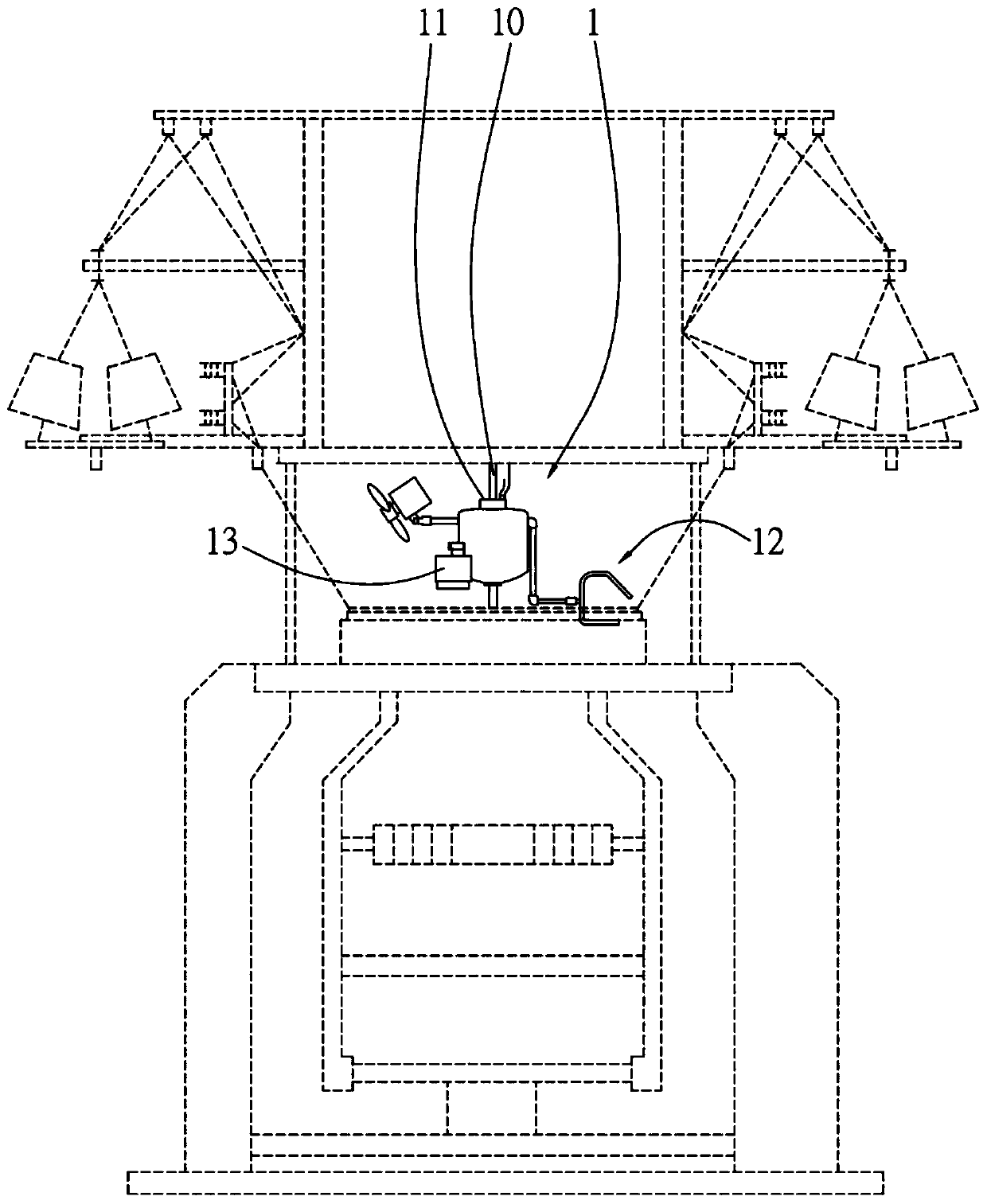
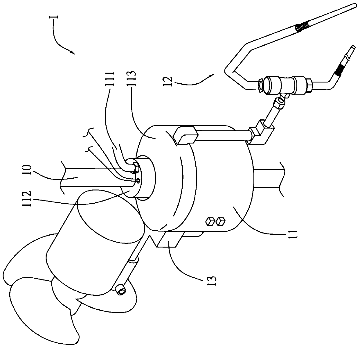
[0003] However, the inner spring of the carbon brush motor 13 uses elastic force to reach the carbon brush, and the friction process causes the carbon brush to be worn out too quickly and a gap is likely to be generated, resulting in poor contact and difficult replacement of the carbon brush, and the carbon brush motor 13 cannot control signals, The interference is too strong, which will cause noise due to the friction of the carbon brush. There is no inspection light to detect power failure and judge the abnormal power supply, which further affects the inability of the fabric receiving machine and the machine table to be synchronized with each other, and the rotation speed is not synchronized with the weaving speed; Furthermore, when the yarn is not pressed very tightly, it is inevitable that cotton wool will continue to accumulate to form cotton balls, and the yarn needle is easy to catch when hooking the yarn, causing the yarn needle to break, which in turn increases the cloth loss rate, and the most important The disadvantage is that the carbon brush motor will easily produce carbon powder, which will generate sparks during high temperature and high-speed friction. Sparks will cause electrical failure or explosion

Method used


Image

  • Flocculent-yarn blowing and heat dissipation improved structure for circular knitting machine
  • Flocculent-yarn blowing and heat dissipation improved structure for circular knitting machine
  • Flocculent-yarn blowing and heat dissipation improved structure for circular knitting machine

Examples


Embodiment Construction

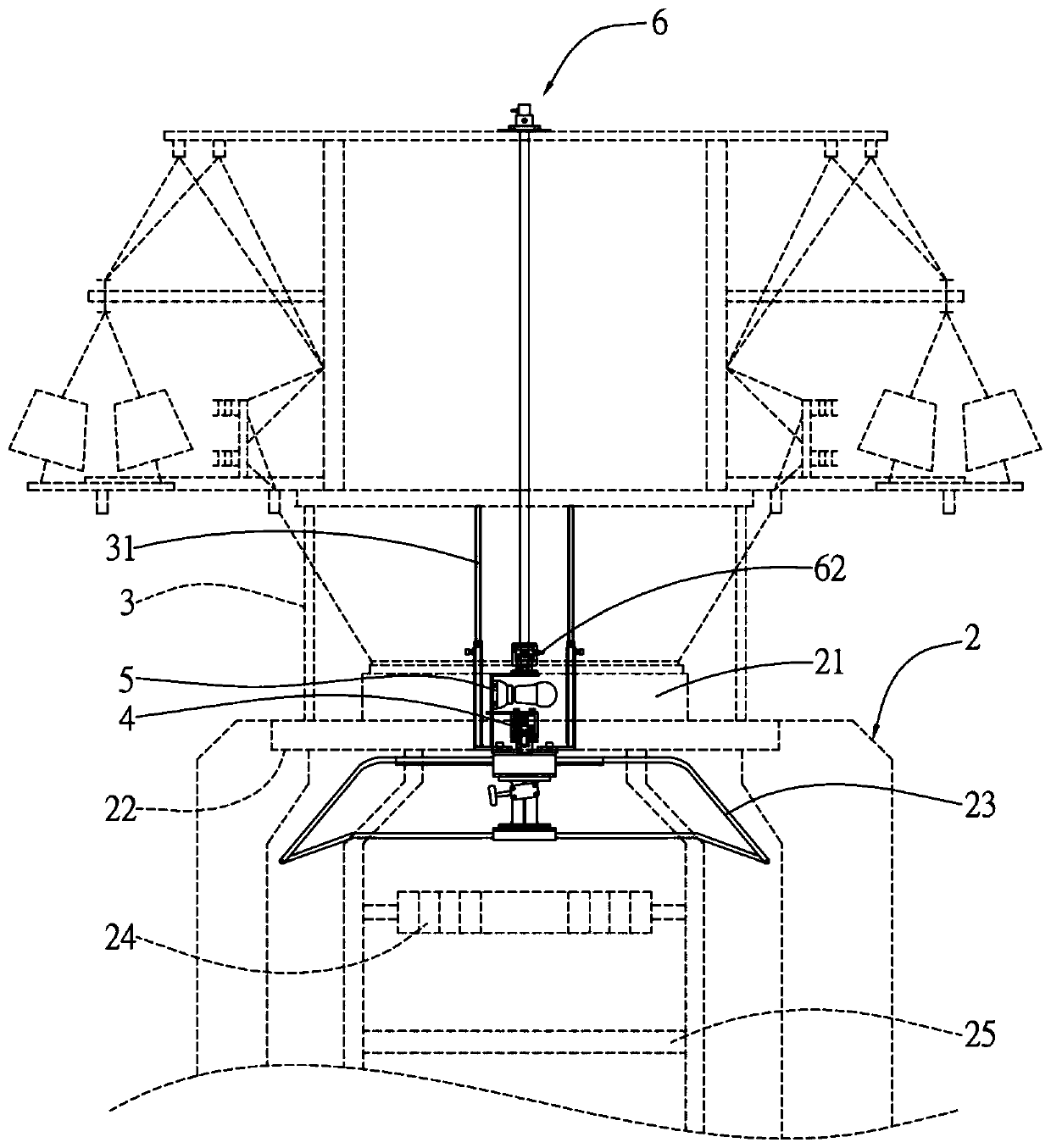
[0028] see Figure 3 to Figure 5 As shown, the structure of the present invention can be seen from the figure, which includes: a machine platform 2, a relative fixed assembly 3, a mercury seat 4, a detection device 5, and a blowing and cooling structure 6;

[0029]The top of the machine table 2 has an upper needle barrel 21, a lower needle barrel 22 with the upper needle barrel 21 connected, and a space for knitted cloth is formed between the bottom of the upper needle barrel 21 and the inner wall of the lower needle barrel 22, and a fabric support frame is extended at the bottom of the bottom 23. A fabric pulling rod 24 and a cloth rolling rod 25 are correspondingly arranged below a cloth support frame 23; a spaced telescopic frame 31 protrudes on both sides of the outer edge of the aforementioned upper needle barrel 21 relative to the fixed assembly 3, and each telescopic frame 31 A telescopic tube 32 is arranged along the telescopic direction, and a plurality of adjusting s...


PUM


Abstract

The invention discloses a flocculent-yarn blowing and heat dissipation improved structure for a circular knitting machine. The improved structure mainly includes a machine table, fixing assemblies, ahydrargyrum base, a monitoring device and a flocculent-yarn blowing and heat dissipation structure body; the symmetrical fixing assembles are fixedly inserted into the outer edge of an upper needle hole of the machine table, the hydrargyrum base is clamped at the position close to the center of the upper needle hole, the monitoring device is arranged above the hydrargyrum base, a first lamp is fixedly assembled on the inner side of a first side edge of one side of a supporting frame of the monitoring device, and the flocculent-yarn blowing and heat dissipation structure body is locked and combined, towards the top surface, with a second side edge of the other side of the supporting frame. By blowing away flocculent yarn to prevent yarn from piling up to form cotton balls, a yarn needle isnot easily entangled, and increasing of the defect rate of the cloth is reduced; meanwhile, by monitoring outage through a checking light, knitting signals when the yarn is knitted are controlled so that noise cannot be generated, and thus it is further achieved that a power supply is not subjected to abnormal efficacy; therefore, the tension is adjusted, and meanwhile the thickness of the cloth is adjusted to be suitable for the tightness of rolling, so that the flocculent-yarn blowing and heat dissipation improved structure for the circular knitting machine is formed.

Description

technical field [0001] The present invention relates to an improved heat dissipation structure of a circular knitting machine by blowing wadding, in particular to a structure that can detect power failure through a test lamp, easily blows the wadding away and prevents the yarn from being caught into cotton balls, and is not easy to make the yarn needle It can reduce the increase of cloth defect rate by hooking, and can control the signal without noise during cloth weaving, further make the power supply normal, and adjust the tension in time and at the same time, adjust the thickness of the cloth to suit the tightness of rolling roll Machine blowing heat dissipation improved structure. Background technique [0002] At present, in response to the changing times and the needs of industrial progress, in order to reduce the cotton wool that is often produced during the weaving process of the circular knitting machine, it will affect the quality and wear of the cloth and further r...

Claims


Application Information

Patent Timeline
Patent Type & Authority Applications(China)
IPC IPC(8): D04B35/32D04B35/30D04B35/14
CPCD04B35/32D04B35/30D04B35/14
Inventor 林进泳
Owner 泳立(厦门)机械有限公司
Learn More