
High-precision RV speed reducer comprehensive testing device

A comprehensive testing and reducer technology, applied in the direction of measuring devices, testing of machine/structural components, testing of mechanical components, etc., can solve the problem of decreased accuracy, low accuracy of assembly process, failure to obtain backlash, backlash and torsion Rigidity and other issues to achieve the effect of simplifying assembly, assembly and disassembly process

Pending Publication Date: 2019-11-22
上海羿弓精密科技有限公司
View PDF2 Cites 10 Cited by
  • Summary
  • Abstract
  • Description
  • Claims
  • Application Information

AI Technical Summary

Problems solved by technology

The utility model patent with the publication number CN206399652U discloses a comprehensive testing device. Although the scheme can measure various parameters, since the magnetic powder brake cannot be actively loaded, the hysteresis curve cannot be tested, so it is impossible to obtain accurate hysteresis, gear backlash and torsional stiffness
[0004] In addition, there are many defects in the existing RV reducer comprehensive test device: 1) the assembly and disassembly process of the RV reducer is more complicated, the accuracy of the assembly process is not high, and it is easy to cause system errors; 2) the adaptability of the sensor is low, There are few reserved installation positions for sensors on the overall device, and it is impossible to realize the adaptive replacement of various sensors; 3) The torque sensor cannot be adapted to small-scale measurement, resulting in a decrease in accuracy, and it cannot be tested under light load; 4) The input shaft is in the The setting position on the bracket makes it difficult to balance the bearing clearance, resulting in system errors; 5) It is difficult to completely fix the input end with the cooperation of the cylindrical rod hole in the prior art; 6) The transmission stability of the input shaft and the coupling needs to be further improved. Improve; 7) The first angle sensor at the input end of the reducer cannot meet the transmission accuracy test at high speed

Method used


Image

  • High-precision RV speed reducer comprehensive testing device
  • High-precision RV speed reducer comprehensive testing device
  • High-precision RV speed reducer comprehensive testing device

Examples


Embodiment

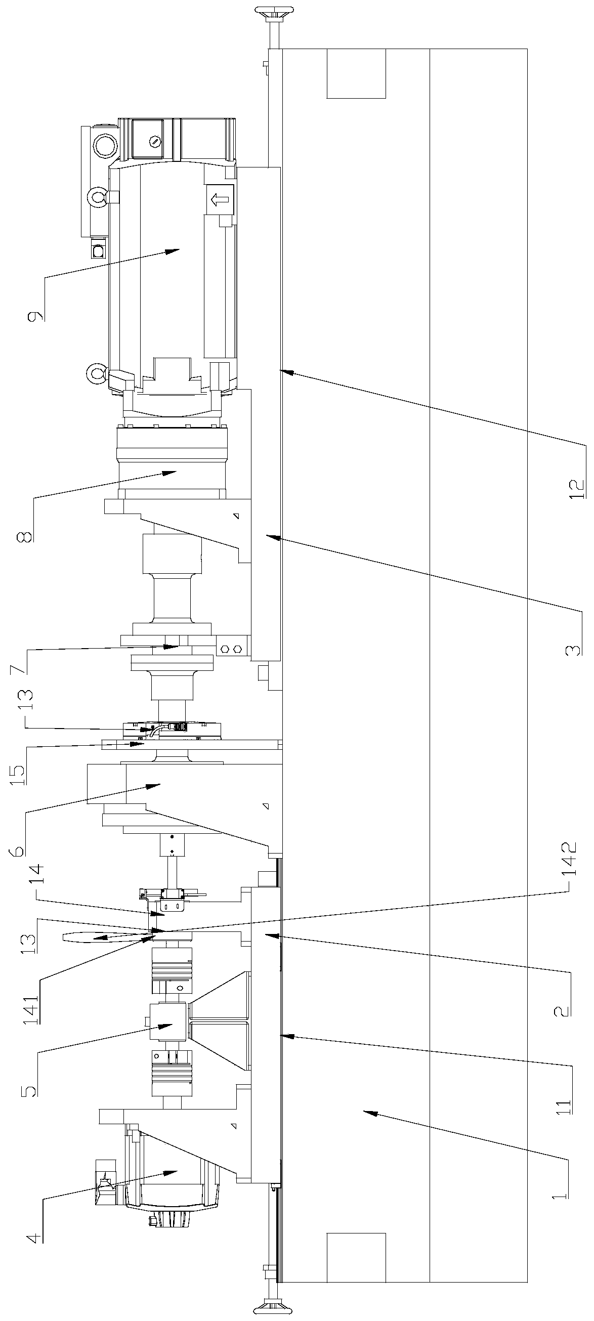
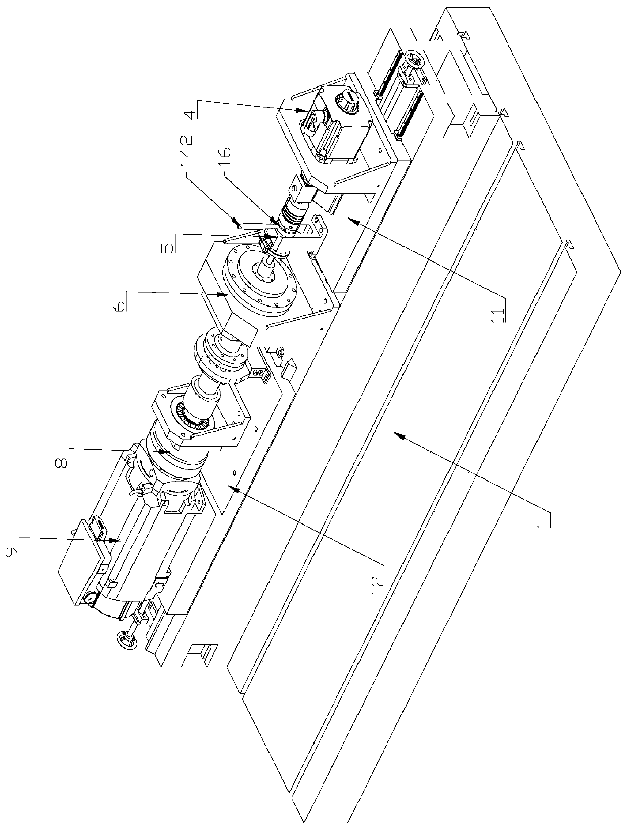
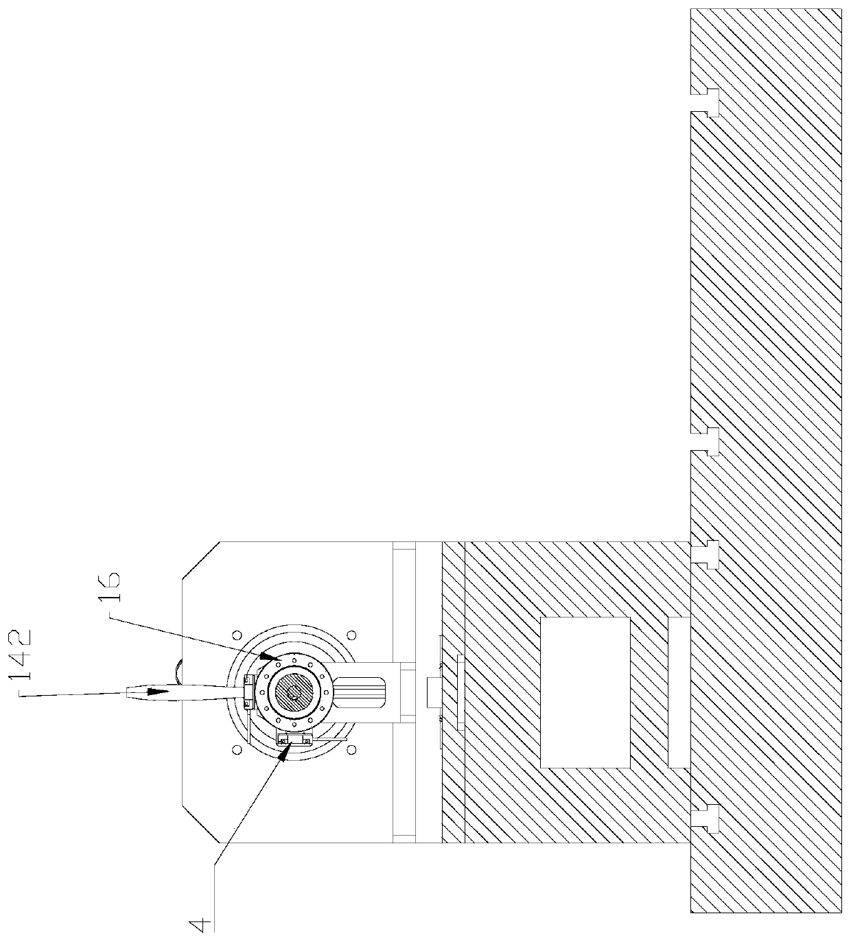
[0046] The high-precision RV reducer comprehensive test device in the present invention includes the following parts:

[0047] Part 1 of the base: a first slide rail 11 and a second slide rail 12 are arranged on it. The first sliding platform 2 is arranged on the first linear slide rail 11, and can be linearly displaced along the first linear slide rail 11; the second sliding platform 3 is arranged on the second linear slide rail 12, and can move along the second straight line The slide rail 12 is linearly displaced, and the RV speed reducer 6 to be tested is arranged between the first sliding platform 2 and the second sliding platform 3 . Both ends of the base 1 are respectively provided with a shaft rod assembly, which realizes the horizontal position adjustment of the first sliding platform 2 and the second sliding platform 3 respectively, and its rod is provided with an external thread, which is compatible with the first sliding platform 2 and the second sliding platform. ...


PUM


Abstract

The invention relates to a high-precision RV speed reducer comprehensive testing device, which comprises a base, a first sliding platform, a second sliding platform, a first motor, a first torque sensor, a second motor, a second torque sensor, a first angle sensor, an input shaft bracket and an output shaft bracket. Compared with the prior art, the high-precision RV speed reducer comprehensive testing device designs the sliding platform assembly capable of being rapidly disassembled and assembled, so that the assembling and disassembling process of an to-be-tested RV speed reducer is more convenient and faster; the output shaft bracket and the input shaft bracket can be used for adapting to the requirements of sensors with different specifications; the limiting parts of the sliding platforms improve the test precision; the double-measuring-range torque sensors can adapt to measurement of speed reducers of different series models, and can also realize test of transmission precision under light load; an input shaft of the to-be-tested RV speed reducer is installed in two bearing inner rings sharing the same horizontal axis, thereby facilitating the adjustment of a bearing clearance;and the double-reading-head circular grating angle sensors meet the requirement that the transmission precision is tested in a high-speed state.

Description

technical field [0001] The invention relates to a reducer comprehensive test device, in particular to a high-precision RV reducer comprehensive test device. Background technique [0002] The RV reducer is a two-stage transmission reducer, the first stage is a planetary transmission, and the second stage is a cycloidal pinwheel transmission. The RV reducer is composed of a cycloidal pinwheel and a planetary bracket. Because of its small size, it is resistant to Strong impact force, large torque, high positioning accuracy, small vibration, large reduction ratio and many other advantages are widely used in industrial robots, machine tools, medical testing equipment and satellite receiving systems and other fields. Compared with the harmonic drive commonly used in robots, it has much higher fatigue strength, stiffness and life, and the backlash accuracy is stable, unlike the harmonic drive, which will significantly reduce the motion accuracy as the use time increases, so many co...

Claims


Application Information

Patent Timeline
IPC IPC(8): G01M13/025
CPCG01M13/025
Inventor 张荣荣沈金理李景敏祁梦颖盛明杰
Owner 上海羿弓精密科技有限公司
Learn More