
Urban rail transit direct-current traction power supply isolation switch interlocking system and method

A technology of urban rail transit and DC traction, applied in the field of rail transit, can solve the problems of poor corrosion resistance of relays and auxiliary contacts, data reception errors, high damage rate of isolating switch interlocking equipment, etc., to reduce the signal transmission channel between stations , Reduce maintenance time and cost, solve the effect of difficult construction and expansion

Active Publication Date: 2019-11-22
NR ENG CO LTD +2
View PDF7 Cites 0 Cited by
  • Summary
  • Abstract
  • Description
  • Claims
  • Application Information

AI Technical Summary

Problems solved by technology

It is usually difficult to detect the abnormality of the cable channel in time, and there is a risk that the switch position signal cannot be transmitted. In particular, the interlocking judgment of the cross-area isolation switch requires the switch position information in the adjacent traction substation, and the signal transmission distance is long, so it can only be passed through regular inspections. 2. The interlocking equipment of the isolating switch is usually placed underground, but the humidity in the underground environment is high, and the corrosion resistance of the relays and auxiliary contacts in the interlocking equipment is poor, which makes the interlocking equipment of the isolating switch have a high damage rate ; 3. The interlocking equipment of the isolating switch realizes the interlocking logic through the conditional connection of the auxiliary contacts in the secondary electrical control circuit. The secondary wiring is many and complicated, which brings great difficulties to the maintenance of the equipment; 4. Phase The switch position information between adjacent traction substations is transmitted through electrical signals. The distance of electrical signal transmission is limited and the anti-interference ability is poor. However, the distance between traction substations in urban rail transit is long, and the electromagnetic interference in the underground environment is large, resulting in The stability of electrical signal transmission is poor, and it is easy to cause data reception errors

Method used


Image

  • Urban rail transit direct-current traction power supply isolation switch interlocking system and method
  • Urban rail transit direct-current traction power supply isolation switch interlocking system and method
  • Urban rail transit direct-current traction power supply isolation switch interlocking system and method

Examples


Embodiment 1

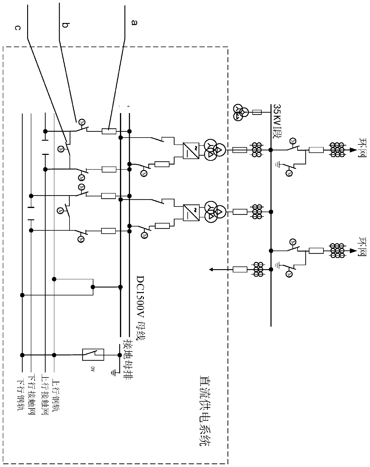
[0035] like figure 1 Shown is a schematic diagram of the urban rail transit DC traction power supply system; in the figure, a-DC circuit breaker, b-grid disconnect switch, c- cross-region disconnect switch. An interlocking system for an isolating switch for urban rail transit DC traction power supply of the present invention includes the following functional equipment:

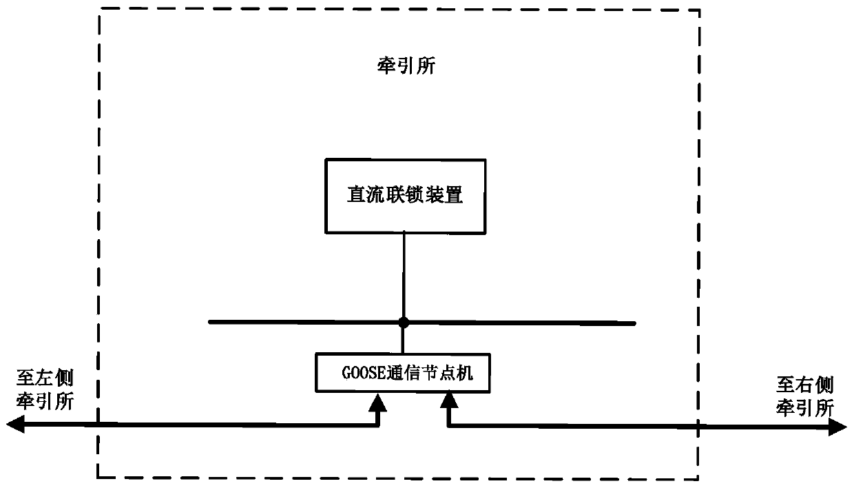
[0036]The GOOSE communication node machine is installed in each traction substation, and the GOOSE communication node machines of different traction substations are cascaded between stations to build a GOOSE network for information sharing of DC power supply system equipment.

[0037] The DC interlocking device is installed in each traction substation to collect the position of each switch in the substation. The DC interlocking device is connected to the GOOSE network through the GOOSE communication node mechanism in the station. like image 3 Shown is a schematic diagram of the intra-station network of the ...

Embodiment 2

[0047] An embodiment of an interlocking method for an urban rail transit DC traction power supply isolating switch, comprising the following steps:

[0048] S1: GOOSE communication node machines are installed in each traction substation, and GOOSE communication node machines in different traction substations are cascaded between stations to build a GOOSE network for information sharing of DC power supply system equipment.

[0049] The inter-station cascading of GOOSE communication nodes adopts "hand in hand" cascading or braided cascading. Braided cascading means that the GOOSE communication node machines of each traction substation are cascaded by station jumping, and the GOOSE communication node machines of the first and last traction substations are connected with the GOOSE communication node machines of the adjacent traction substations at the same time. cascade. After the physical disconnection of the braided cascaded GOOSE network, the reconstruction of the GOOSE networ...


PUM


Abstract

The invention discloses an urban rail transit direct current traction power supply isolation switch interlocking system and method, and the method comprises the following steps: setting GOOSE communication node machines in all traction substations, carrying out the inter-station cascading of all communication node machines, and constructing a GOOSE network for the equipment information sharing ofa DC power supply system. A direct current interlocking device is arranged in each traction substation, collects the position of each switch in the substation, and is connected to the GOOSE network through a GOOSE communication node mechanism in the substation. And the direct current interlocking device builds interlocking logics of isolation switch operation according to the switch position information of the local and other traction substations, and determines whether the isolation switch in the substation can perform switching-on and switching-off operation or not according to a logic judgment result. According to the scheme of the invention, the intelligent level and reliability of operation interlocking of the isolation switch are greatly improved, the complexity of interlocking logic implementation is reduced, the efficiency of engineering implementation and operation and maintenance is improved, and the maintenance time and cost of operation and maintenance personnel for the system are reduced.

Description

technical field [0001] The invention belongs to the technical field of rail transit, and in particular relates to an interlocking system and method of an isolating switch for DC traction power supply of urban rail transit. Background technique [0002] As an important part of the urban rail transit system, the DC traction power supply system provides electric energy to electric vehicles through the DC traction catenary. The isolating switch is the main power stop and transmission control equipment that connects the DC traction catenary system and the power supply system of the traction substation. Ensure the safety of maintenance personnel and maintenance equipment; 2. According to the needs of power supply, open and close operations are performed to change the working status of the power supply system and improve the flexibility of power supply. In order to prevent accidents such as abnormal power outages of the DC power supply system, equipment damage, and even personal c...

Claims


Application Information

Patent Timeline
Patent Type & Authority Applications(China)
IPC IPC(8): H02J1/00H02J13/00
CPCH02J1/00
Inventor 刘永生何治新侯炜陈吉刚陈俊赵美君张晔李鲲鹏李宇琦魏巍
Owner NR ENG CO LTD
Learn More