A blowing-in-one foam board depowder machine
What is Al technical title?
Al technical title is built by PatSnap Al team. It summarizes the technical point description of the patent document.
A technology of foam boards and racks, applied in the direction of removing smoke and dust, using gas flow cleaning methods, cleaning methods and appliances, etc., can solve the problems of dust residue on the surface of foam boards, to ensure cleanliness, avoid environmental pollution, The effect of improving quality and work efficiency
Inactive Publication Date: 2020-08-04
QINGDAO UNIV OF SCI & TECH
View PDF14 Cites 0 Cited by
Summary
Abstract
Description
Claims
Application Information
AI Technical Summary
This helps you quickly interpret patents by identifying the three key elements:
Problems solved by technology
Method used
Benefits of technology
Problems solved by technology
[0003] The purpose of the present invention is to overcome the deficiencies of the prior art, fundamentally solve the problem of dust residue on the surface of foamed boards, and provide a foamed board dedusting machine that combines two pairs of blowing and purging into one. The roller cleans and blows the dust on the surface of the foam board, and the upper and lower surfaces are cleaned synchronously, which ensures the cleanliness of the foam board surface, greatly improves the quality and work efficiency of the foam board, and relieves the heavy physical labor of the workers
Method used
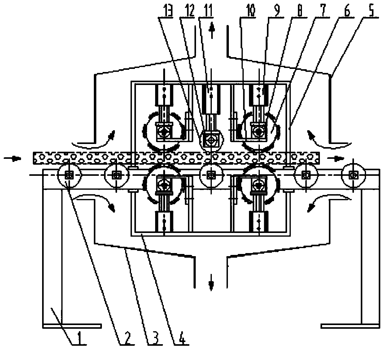
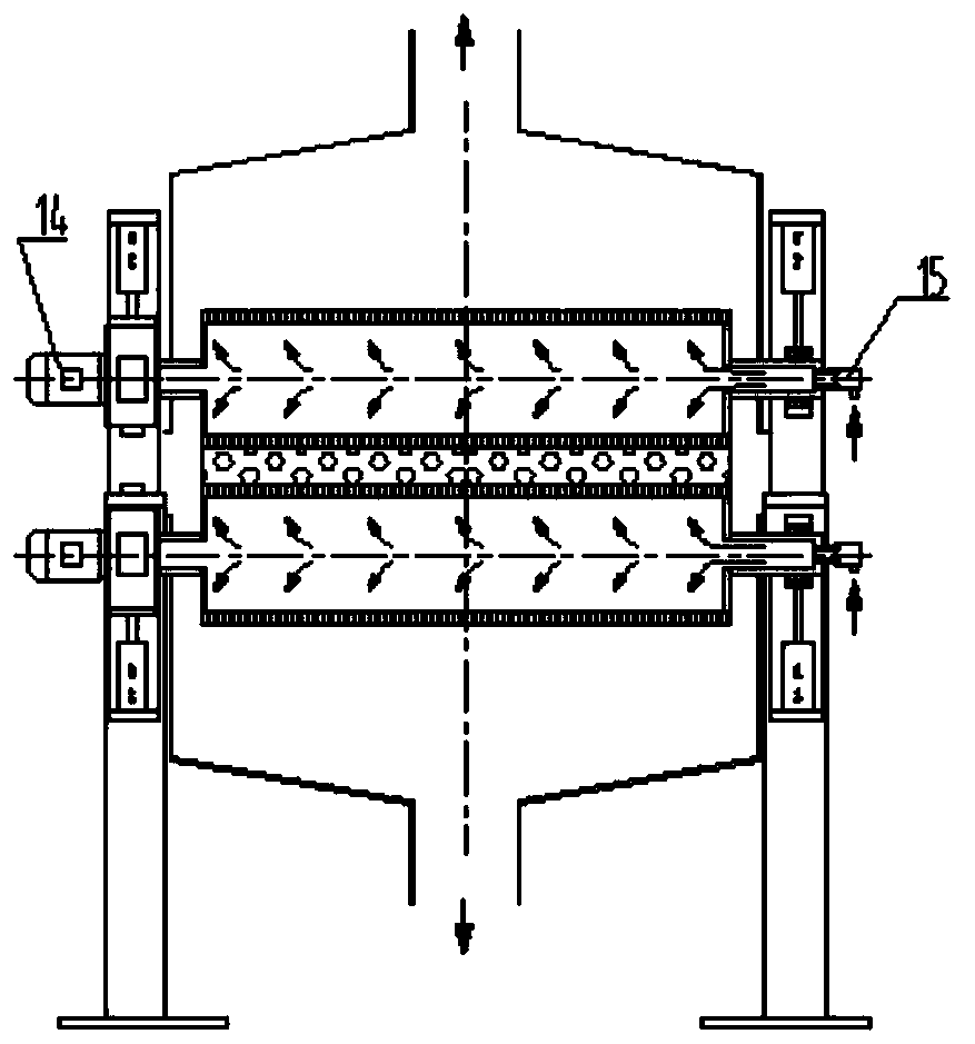
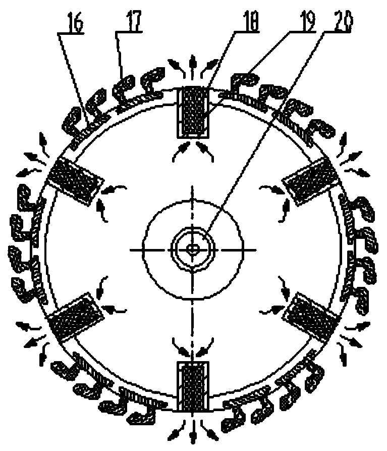
Image
Click on the blue label to locate the original text in one second.
Reading with bidirectional positioning of images and text.
Examples
Embodiment Construction
[0019] The specific implementation manners of the present invention will be further described in detail below in conjunction with the accompanying drawings.
[0020] combine figure 1 , figure 2 and image 3 As shown, a blowing-in-one foam board depowder machine includes a frame 1, an electric roller 2, a lower dust cover 3, a lower bracket 4, an upper dust cover 5, an upper bracket 6, a blower Sweeping roller 7, blowing bearing with seat 8, blowing cylinder 9, adjustable limit plate 10, pressing cylinder 11, pressing bearing with seat 12, pressing roller 13, motor reducer 14, rotary joint 15, all The blowing roller 7 includes a roller body 16 , a brush 17 , a nozzle seat 18 , a filter nozzle 19 , and a journal 20 . Described electric roller 2 is arranged on frame 1, and frame 1 two sides are respectively fixed with upper bracket 6 and lower bracket 4, and upper bracket 6 and lower bracket 4 each have 2 pieces, are gantry structure form. Described adjustable limit plate 10...
PUM
Abstract
The invention relates to a blowing and sweeping integrated foaming plate powder removing machine which comprises a machine frame, an electric roller, an upper dust hood, a lower dust hood, upper brackets, lower brackets, blowing rollers, blowing belt seat bearings, blowing air cylinders, adjustable limiting plates, a pressing cylinder, a pressing belt seat bearing, a pressing roller, a motor reducer and a rotary joint. Each blowing roller comprises a roller body, a brush, a nozzle seat, a filtering nozzle and a shaft neck. Along with the rotation of the blowing rollers, the brushes embedded onthe circumferences of the blowing rollers clean the dust attached to the surface of a foaming plate, meanwhile, the compressed air ejected from the circumferences of the blowing rollers lifts the dust from the surface of the foaming plate, and the blowing rollers simultaneously clean and blow the upper surface and the lower surface of the foaming plate. By adopting the dust suction mode that theupper dust hood and the lower dust hood suck wind and gather the wind and then filtering treatment of a dust remover is started, the raised dust is collected and treated in time, so that the quality of the foaming plate is improved, heavy physical labor of workers is relieved, the working efficiency is improved, the environmental pollution is avoided, the collected dust can be recycled, and the material cost is reduced.
Description
technical field [0001] The invention relates to the technical field of environmental protection and dedusting, in particular to a blowing-in-one foam plate dedusting machine. Background technique [0002] Foam board is based on plastic (PVC, PET, etc.), with catalysts, foam stabilizers, foaming agents and other auxiliary materials, and then cut after foaming. Because of its light weight and functions of cushioning, sound absorption, shock absorption, heat preservation, and filtration, it is widely used in industries such as mechanical equipment, rail transit, yachts, aerospace, and building energy conservation. There is a lot of fine dust on the surface of the cut foam board. If it is packaged and shipped without cleaning, it will inevitably cause dust to fly during transportation or installation and use, seriously pollute the environment, and even cause quality accidents, and may cause damage to the site. The health of the operator will be affected. The current method is ...
Claims
Application Information
Patent Timeline
Application Date:The date an application was filed.
Publication Date:The date a patent or application was officially published.
First Publication Date:The earliest publication date of a patent with the same application number.
Issue Date:Publication date of the patent grant document.
PCT Entry Date:The Entry date of PCT National Phase.
Estimated Expiry Date:The statutory expiry date of a patent right according to the Patent Law, and it is the longest term of protection that the patent right can achieve without the termination of the patent right due to other reasons(Term extension factor has been taken into account ).
Invalid Date:Actual expiry date is based on effective date or publication date of legal transaction data of invalid patent.