A Classified Scheduling Method and Device Adapting to Time-Triggered Networks
A scheduling method and time-adapting technology, applied in data exchange networks, digital transmission systems, electrical components, etc., can solve problems such as high requirements for software and hardware logic coupling, high software logic complexity, and low synchronization accuracy, and achieve clock accuracy Affects the effects of reducing, improving accuracy, and reducing dwell time
- Summary
- Abstract
- Description
- Claims
- Application Information
AI Technical Summary
Problems solved by technology
Method used
Image
Examples
Embodiment 1
[0072] In the prior art, time synchronization is required for scheduling various frames, and time synchronization between devices requires calculation of the link delay between devices; in the prior art, the prior art obtains the link delay based on the IEEE1588 protocol to calculate the link delay, which requires The upper-layer software sends and receives PTP frames, and sends them to the hardware and then to the peer. The hardware is responsible for adding time stamps on it, and the software calculates the delay value. Obtaining the link delay through software methods increases the logic complexity of the upper layer software and the coupling degree of software and hardware logic, and also reduces the accuracy of link delay measurement; therefore , this application proposes a classification scheduling method to improve the calculation of link delay, the details are as follows:
[0073] Definition of technical terms: time-triggered frame-TT frame, link delay measurement fram...
Embodiment 2
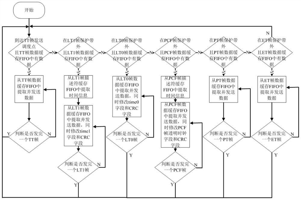
[0090] Based on Embodiment 1, the scheduling details of various types of frames are refined, and the dynamic path delay corresponding to the PCF frame entering the buffer to the output buffer is recorded in the transparent clock field of the PCF frame when the PCF frame is scheduled to be sent to ensure the accuracy of the PCF frame sent by the port. The transparent clock field Transparent Clock is equal to the delay experienced by the PCF frame to optimize clock synchronization; while scheduling and sending ET frames, it also schedules and sends flow control frames PT frames to prevent ET frames from blocking flow control frames and ensure that flow control is timely Execution ensures the normal transmission of time-triggered frames and maximizes the transmission rate and stability of ordinary Ethernet frames; the details are as follows:
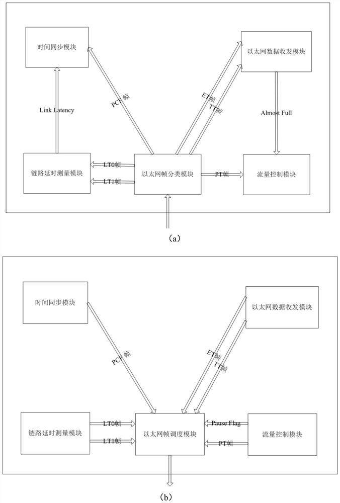
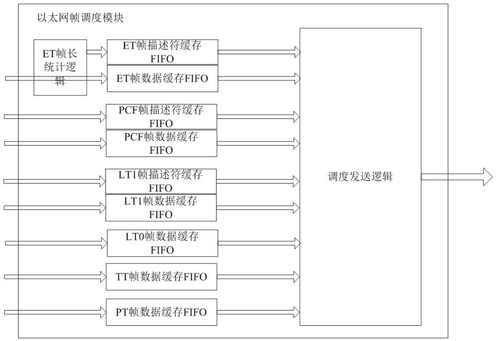
[0091] Such as figure 1 , 4 As shown, it is divided into the sending frame direction and the receiving frame direction, the 0 port is the...
Embodiment 3
[0114] Based on embodiment 1 or 2, a kind of device is proposed, and described device comprises
[0115] The Ethernet frame scheduling module is used to receive various frame data and indication signals sent by the upper module, store the frame data in the corresponding buffer FIFO, and then cache the FIFO status and The local clock sends various frames;
[0116] The Ethernet frame classification module is used to receive the Ethernet frame, and send various frames to the corresponding upper layer module according to the TYPE field of the Ethernet frame;
[0117] The link delay measurement module is used to generate LT0 frames and LT1 frames to measure the link delay of the port and the port, and periodically provide link delay for the local time synchronization module;
[0118]The time synchronization module is used to correct the local clock by receiving the PCF frame sent by the Ethernet frame classification module, and provides a synchronized local clock for the local Eth...
PUM
 Abstract
Description
Claims
Application Information
 - R&D
- Intellectual Property
- Life Sciences
- Materials
- Tech Scout
- Unparalleled Data Quality
- Higher Quality Content
- 60% Fewer Hallucinations
Browse by: Latest US Patents, China's latest patents, Technical Efficacy Thesaurus, Application Domain, Technology Topic, Popular Technical Reports.
© 2025 PatSnap. All rights reserved.Legal|Privacy policy|Modern Slavery Act Transparency Statement|Sitemap|About US| Contact US: help@patsnap.com


