Array Amplitude and Phase Error Estimation Method Based on Sparse Reconstruction Algorithm
An array amplitude-phase error and amplitude-phase error technology, which is applied in the field of array amplitude-phase error estimation based on sparse reconstruction algorithm, can solve the problems that affect the estimation result, the amount of adjusting the clutter spectral sparsity is difficult to determine, etc., and achieve the estimated value Accurate, reduce the number of solutions, improve the effect of the effect
- Summary
- Abstract
- Description
- Claims
- Application Information
AI Technical Summary
Problems solved by technology
Method used
Image
Examples
Embodiment 1
[0062] See figure 1 , figure 1 yes figure 1 It is a flowchart of an array amplitude and phase error estimation method based on a sparse reconstruction algorithm provided by an embodiment of the present invention. As shown in the figure, the array amplitude and phase error estimation method based on a sparse reconstruction algorithm in this embodiment includes:
[0063] S1: Obtain the space-time data Y received by the antenna array;
[0064] Specifically, the space-time data Y received by the antenna array is obtained according to the number N of array elements and the number L of pulses,
[0065]
[0066] Among them, Φ represents the standard array flow pattern dictionary matrix, X represents the clutter spectrum, Indicates the amplitude and phase error of the real array, and N indicates the number of array elements.
[0067] S2: Initialize the additive amplitude and phase error p k , according to the additive amplitude and phase error p k , construct a dictionary ma...
Embodiment 2
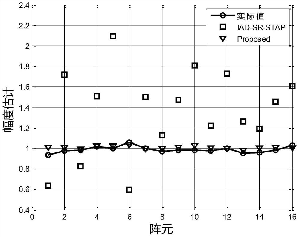
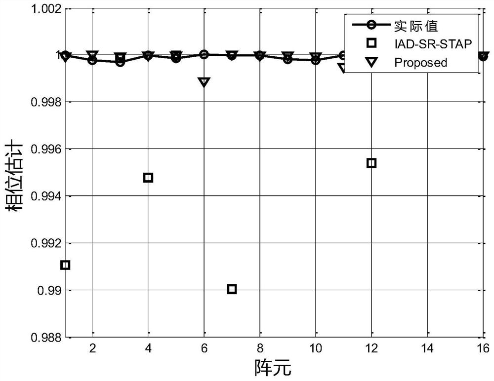
[0106] In this embodiment, a simulation experiment is performed on the array amplitude and phase error estimation method based on the sparse reconstruction algorithm in the first embodiment, to further illustrate the effect of the method of the present invention.
[0107] In this embodiment, the antenna array structure adopts a uniform linear array, the number of array elements N is 16, the distance between the array elements is d=λ / 2, the number of pulses L is 4, and only the azimuth dimension is considered. The simulation of this embodiment The experiment uses the Ward clutter model for clutter simulation, and adds random white noise. The simulation parameters are shown in Table 1.
[0108] Table 1 Simulation parameters
[0109] platform speed 100m / s antenna array 16X1 line array Number of pulses 4 repeat frequency 4000Hz main beam pointing (0°) noise-to-noise ratio 20dB
[0110] In this embodiment, the IAD-SR-STAP algorithm ...
PUM
 Abstract
Description
Claims
Application Information
 - R&D
- Intellectual Property
- Life Sciences
- Materials
- Tech Scout
- Unparalleled Data Quality
- Higher Quality Content
- 60% Fewer Hallucinations
Browse by: Latest US Patents, China's latest patents, Technical Efficacy Thesaurus, Application Domain, Technology Topic, Popular Technical Reports.
© 2025 PatSnap. All rights reserved.Legal|Privacy policy|Modern Slavery Act Transparency Statement|Sitemap|About US| Contact US: help@patsnap.com


