
Circularly polarized waveguide slot array antenna

A technology of circularly polarized waves and array antennas, applied in slot antennas, antennas, antenna arrays, etc., can solve the problems of limited design range, inflexible design, narrow bandwidth, etc., and achieve flexible design, simple and compact structure, and small size Effect

Inactive Publication Date: 2019-11-29
10TH RES INST OF CETC
View PDF13 Cites 8 Cited by
  • Summary
  • Abstract
  • Description
  • Claims
  • Application Information

AI Technical Summary

Problems solved by technology

All of the above structures have some disadvantages. The inclined cavity structure has structural interference phenomenon when the inclination angle is large, the design is not flexible enough, and the design range is limited; The resonance characteristics of the structure, the bandwidth is relatively narrow

Method used


Image

  • Circularly polarized waveguide slot array antenna
  • Circularly polarized waveguide slot array antenna

Examples


Embodiment Construction

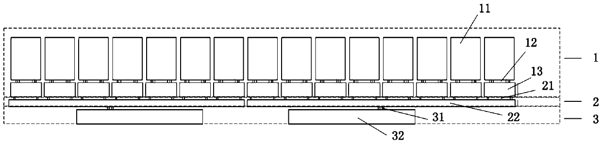
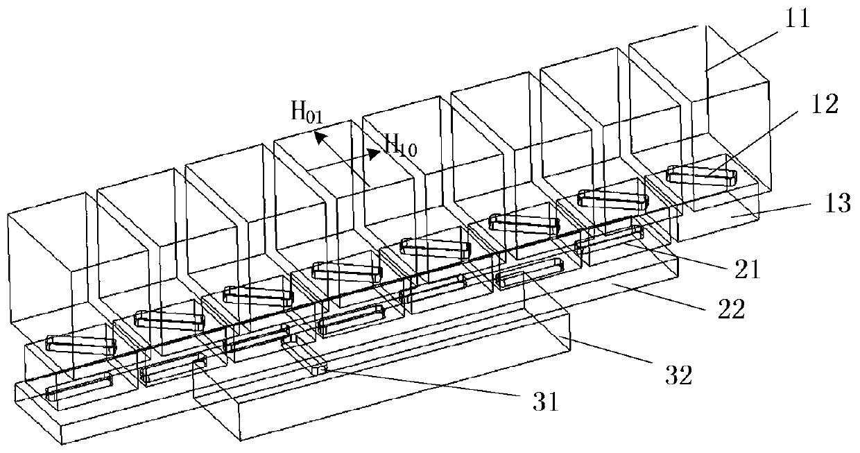
[0014] refer to figure 1 . In an embodiment described below, a circularly polarized waveguide slot array antenna includes: a circularly polarized radiator 1, a waveguide coupling linear array 2, and a feed network 3, wherein: the circular polarizer 1 is arranged by a linear array The rectangular radiation cavity 11 and the corresponding rectangular transition cavity 13 are formed, and the bottom of each rectangular radiation cavity 11 is formed with an inclined slot 12, thereby forming a circularly polarized radiation unit; the bottom of each rectangular transition cavity 13 is formed with a waveguide broadside longitudinal Slit 21 and its vertically connected coupling waveguide 22, coupling waveguide 22 and the broadside longitudinal slit 21 thereon form waveguide coupling line array 2; waveguide coupling line array 2 is vertically connected to feed Electric waveguide 32, waveguide broadside transverse slot 31 and feeding waveguide 32 form a feeding network; radiation signal...


PUM


Abstract

The invention discloses a circularly polarized waveguide slot array antenna, which aims to provide a circularly polarized waveguide slot array antenna with high efficiency, low sidelobe and wide frequency band. According to the technical scheme, a circular polarizer is composed of rectangular radiation cavities arranged in a linear array mode and corresponding rectangular transition cavities, an inclined slot is formed in the bottom of each rectangular radiation cavity, and therefore, a circularly polarized radiation unit is formed; the bottom of each rectangular transition cavity is providedwith a waveguide broadside longitudinal slot and a coupling waveguide vertically connected with the waveguide broadside longitudinal slot, and the coupling waveguide and the broadside longitudinal slot on the coupling waveguide form a waveguide coupling linear array; the waveguide coupling linear array is vertically connected with a feed waveguide through a waveguide broadside transverse slot formed below the waveguide coupling linear array; radiation signals are distributed to the waveguide coupling linear array through the feed network, and the signals are coupled to the circularly polarizedradiator through the waveguide broadside longitudinal slot on the waveguide coupling linear array to form circularly polarized signals and radiate the circularly polarized signals to the outside. Thecircularly polarized waveguide slot array antenna is simple and compact in structure, flexible in design and very suitable for a high-efficiency low-sidelobe broadband circularly polarized antenna array.

Description

technical field [0001] The invention relates to a circularly polarized waveguide slot array antenna applied to satellite communication and interrogation identification systems. Especially suitable for achieving high efficiency, low sidelobe and wide frequency band. Background technique [0002] Slotted waveguide antenna (slotted waveguide antenna) is an antenna that cuts a narrow slit on the waveguide wall or narrow wall according to certain rules to generate electromagnetic wave radiation. The electromagnetic wave transmitted in the waveguide can radiate to the outside through the slot. Because the waveguide slot array antenna has the advantages of high caliber efficiency, high gain, low sidelobe design flexibility, small size, light weight, high reliability, and good environmental adaptability, the circularly polarized waveguide slot array antenna is an advantage of the traditional waveguide slot array antenna. The practical antenna form developed on the basis is widely u...

Claims


Application Information

Patent Timeline
IPC IPC(8): H01Q21/08H01Q21/00H01Q13/10H01Q1/50H01Q1/36
CPCH01Q1/36H01Q1/50H01Q13/10H01Q21/0043H01Q21/08
Inventor 刘熠志李峰于慧娟
Owner 10TH RES INST OF CETC
Learn More