
High-integration anti-unmanned aerial vehicle system and method

An anti-drone, command and control system technology, applied in the field of highly integrated anti-drone systems, to achieve the effect of simple operation, high degree of integration, and easy deployment

Pending Publication Date: 2019-12-03
中国航天系统科学与工程研究院
View PDF6 Cites 11 Cited by
  • Summary
  • Abstract
  • Description
  • Claims
  • Application Information

AI Technical Summary

Problems solved by technology

[0005] The technical problem solved by the present invention is: to overcome the deficiencies of the prior art, to provide a highly integrated anti-drone system and method, aiming at the problem of inconsistent coordinate systems between various devices and the problem of occlusion between devices, the design It is very necessary to develop a highly integrated vehicle-mounted / fixed-mounted anti-UAV system that integrates command and control, radar, photoelectric, radio detection, suppression of interference, and navigation deception equipment. Simple, high reliability and many other advantages

Method used


Image

  • High-integration anti-unmanned aerial vehicle system and method
  • High-integration anti-unmanned aerial vehicle system and method
  • High-integration anti-unmanned aerial vehicle system and method

Examples


Embodiment 1

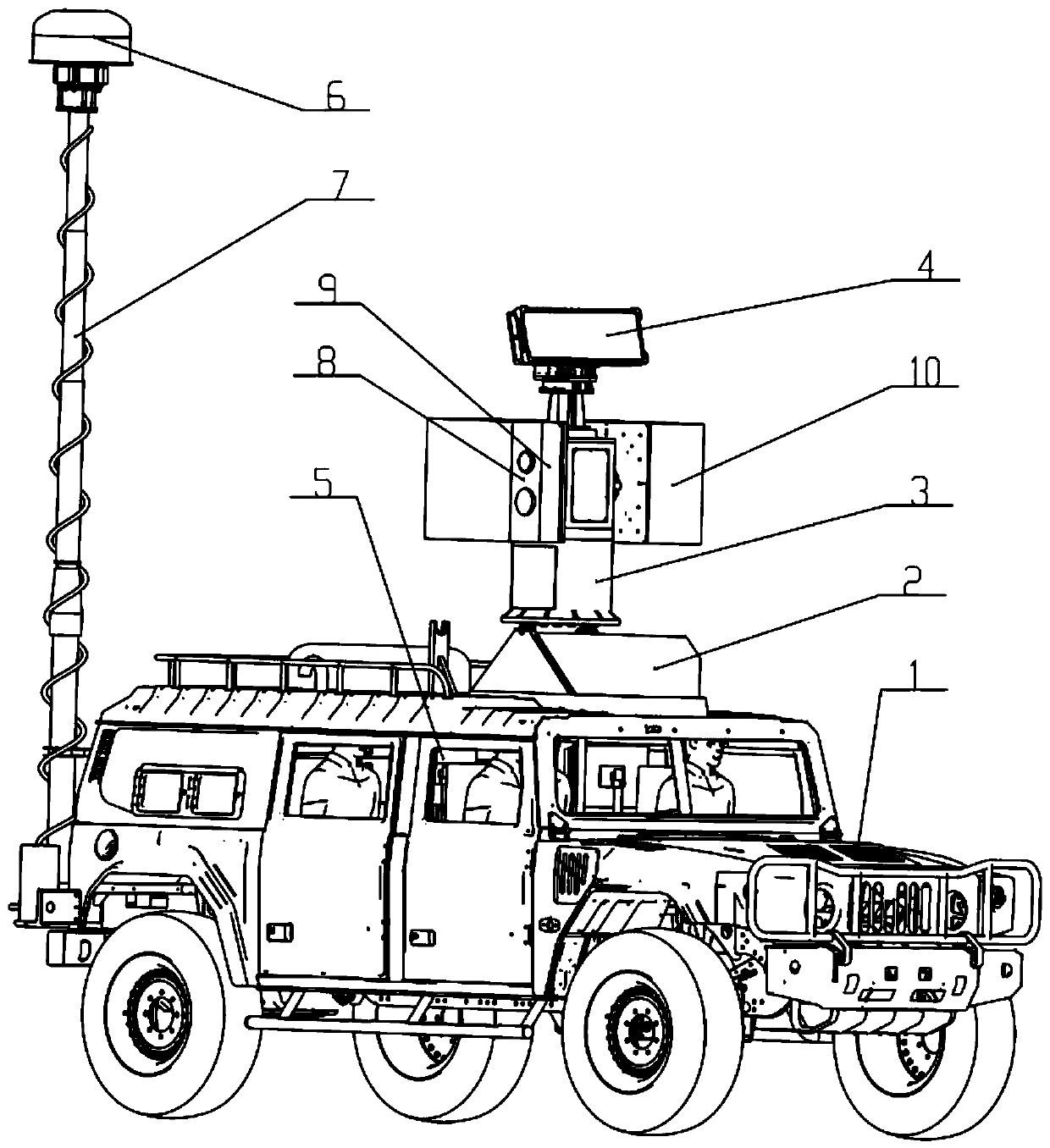
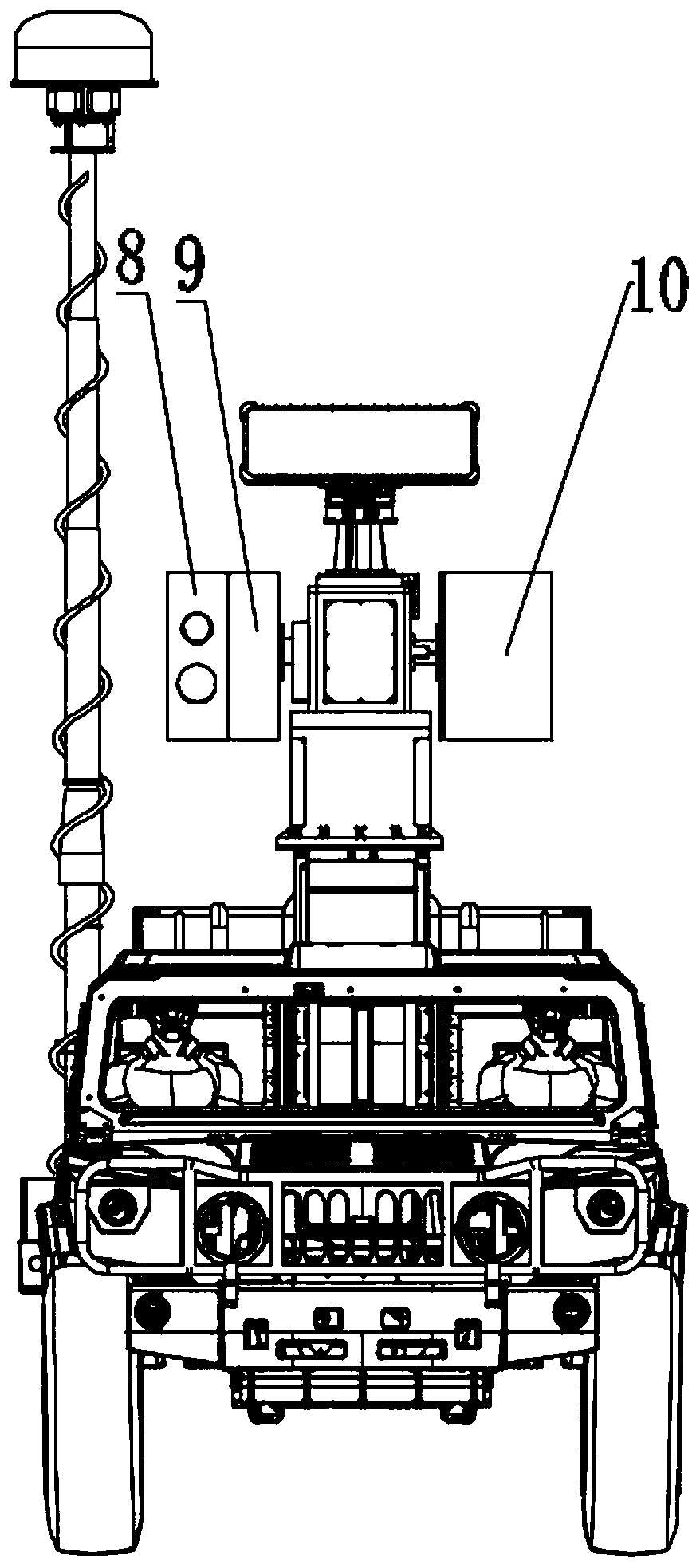
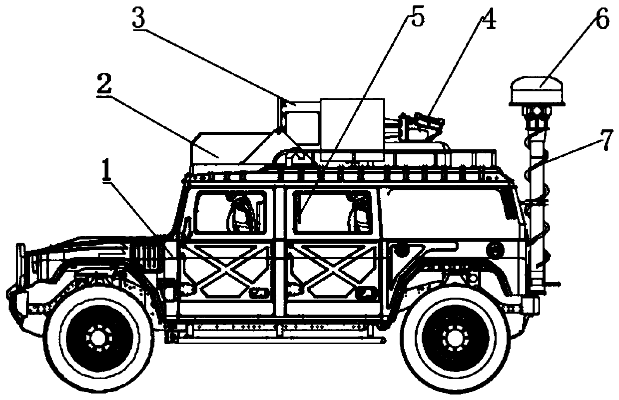
[0034] Such as figure 1 , 2 , 3, and 4, a highly integrated anti-UAV system of the present invention includes a vehicle chassis 1, a servo turntable lodging mechanism 2, a servo turntable 3, radar equipment 4, command and control system equipment 5, radio detection 6. Electric lifting rod 7, photoelectric equipment 8, navigation decoy equipment 9, suppressing interference equipment 10, azimuth part 31 under the servo turntable, pitch part 32 of the servo turntable, and azimuth (reversal mechanism) part 33 above the servo turntable.

[0035] The radio detection equipment 6 is used to detect the target, and sends the detected target prior information to the command and control system equipment 5; the radar equipment 4, the photoelectric equipment 8, the navigation decoy equipment 9 and the suppression interference equipment 10 are all installed on the servo turntable 3 above; the radar device 4 tracks and measures the distance, azimuth, motion speed and pitch angle of the targe...

Embodiment 2

[0044] Such as Figure 5 As shown, a highly integrated anti-drone system of the present invention is also suitable for fixed installation, that is, the servo turntable 3, that is, the electric lifting rod 7, is directly connected to the ground, and the power supply method can be powered by commercial power or oil generator. , each task equipment (servo turntable 3, radar equipment 4, radio detection equipment 6, photoelectric equipment 8, navigation deception equipment 9, suppression interference equipment 10) communicates with the command and control center computer room through RJ45 network interface or optical fiber or mobile communication. The computer is connected to the computer, and the computer can read the status of each task equipment, issue instructions and receive equipment to report information, etc. When the fixed installation is fixed, the servo turntable 3 and the electric lifting rod 7 can pass through after the first installation. Coordinate system conversion...


PUM


Abstract

The invention discloses a high-integration anti-unmanned aerial vehicle system and method, and belongs to the technical field of anti-unmanned aerial vehicles. According to the invention, the problemof non-uniform coordinate systems among all devices and the problem of shielding among the devices are solved, and the high-integration level vehicle-mounted / fixedly-erected anti-unmanned aerial vehicle system integrating the command and control, radar, photoelectricity, radio detection, interference suppression and navigation decoy equipment as one is designed and comprises a servo rotary table,a radar device, a command and control system device, a radio detection device, a photoelectric device, a navigation decoy device and an interference suppression device. The system and the method havethe advantages of complete functions, small size, simple operation, high reliability and the like.

Description

technical field [0001] The invention relates to a highly integrated anti-drone system and method, belonging to the technical field of anti-drone. Background technique [0002] With the rapid development of UAV technology, UAV not only plays an important role in the military field, but also has been widely used in the civilian field. However, with the continuous reduction of the difficulty of use, while drones bring great convenience to people's production and life, their "black flying" and abuse have also caused safety hazards to the country, society and people. [0003] At present, the anti-drone system equipment is mostly composed of detection, tracking and identification equipment, interception and disposal equipment, and command and control center. Detection, tracking and identification equipment mainly includes radar equipment, photoelectric equipment and radio detection equipment; interception and disposal equipment mainly includes suppressing interference and navigat...

Claims


Application Information

Patent Timeline
Patent Type & Authority Applications(China)
IPC IPC(8): F41H11/02
CPCF41H11/02
Inventor 李宗华谢平刘大鹏王瑞顔益安肖楠徐春云孙黎明潘柏臣黎雨楠
Owner 中国航天系统科学与工程研究院
Learn More