Millimeter wave communication system based on directional antenna with fixed direction

A directional antenna and communication system technology, applied in the field of millimeter-wave communication systems, can solve the problems of inconsistency in shell shape affecting antenna performance, complicated calibration, high line density, etc., and achieve power-saving tracking algorithm, simple structure, and simple tracking algorithm Effect

Pending Publication Date: 2019-12-03
AKM ELECTRONICS INDAL PANYU
View PDF0 Cites 6 Cited by
  • Summary
  • Abstract
  • Description
  • Claims
  • Application Information

AI Technical Summary

Problems solved by technology

[0003] However, this traditional antenna array method requires multiple millimeter-wave circuits to work at the same time. Because it uses a power divider and a digitally controlled phase shifter, the circuit processing cost is high, and the amplitude and phase alignment between each channel is also very complicated. also bigger
In addition, the beamforming algorithm is more complicated
In short, the traditional method of relying on antenna arrays to complete beamforming and tracking has the disadvantages of high power consumption, complex circuits, complex calibration, and complex algorithms.
[0004] At the same time, the general AiP (antenna in package) method is not conducive to the flexible design of integrators (such as mobile phone integrators)
For example, the design of the millimeter-wave antenna in the design of the double-sided screen and the metal frame is more difficult to solve
If the antenna is designed based on the screen, the traditional phased array method is difficult to achieve high light transmission due to the high line density, and the phase-shifting array in a thin space. In addition, the AiP antenna is located inside the mobile phone, and the loss and shape inconsistency of the shell will also affect Antenna performance

Method used


Image

  • Millimeter wave communication system based on directional antenna with fixed direction
  • Millimeter wave communication system based on directional antenna with fixed direction
  • Millimeter wave communication system based on directional antenna with fixed direction

Examples


Embodiment Construction

[0039] The preferred embodiments of the present invention will be described below in conjunction with the accompanying drawings. It should be understood that the preferred embodiments described here are only used to illustrate and explain the present invention, and are not intended to limit the present invention.

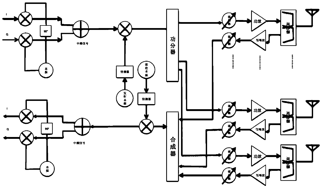
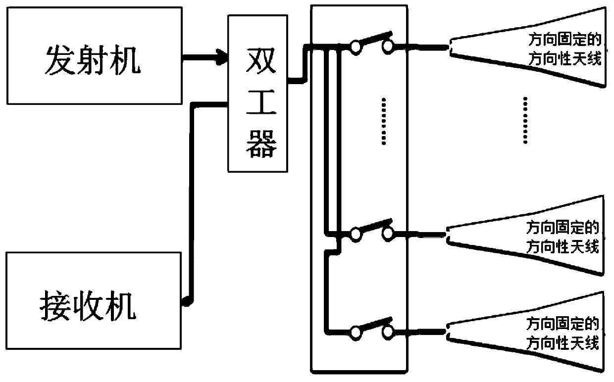
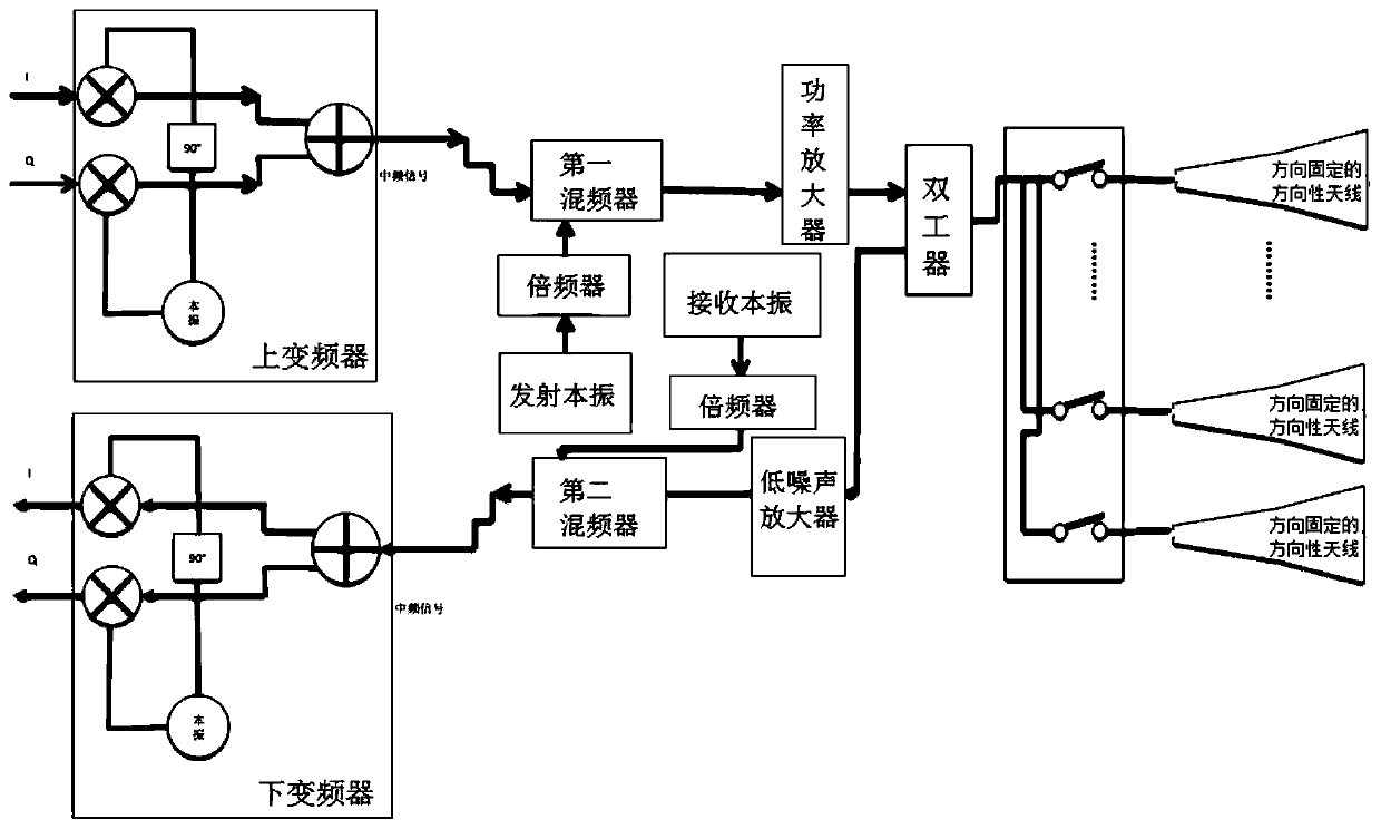
[0040] Such as figure 2 As shown, this specific embodiment discloses a millimeter wave communication system based on a directional antenna with a fixed direction, including a transmitter, a receiver, and multiple antennas. Specifically, the output terminal of the transmitter used to generate the transmitting antenna signal is connected to multiple antennas; a switch is provided on the connection path between each antenna and the output terminal of the transmitter. Specifically, the input terminal of the receiver for receiving antenna signals is connected to a plurality of switches to be connected to a plurality of antennas. Specifically, the multiple antennas incl...


PUM


Abstract

The invention discloses a millimeter wave communication system based on directional antennas with a fixed direction, and the system comprises a transmitter which is used for generating a transmittingantenna signal, and the output end of the transmitter is connected to a plurality of antennas; a switch is arranged on a connecting path of each antenna and the output end of the transmitter; the input end of the receiver is connected to the plurality of switches so as to be connected to the plurality of antennas; the plurality of antennas includes a plurality of directional antennas fixed in a plurality of directions, and the plurality of directional antennas fixed in the plurality of directions are arranged to face a plurality of different directions in a fixed manner. The millimeter wave communication system disclosed by the invention has the characteristics of simple structure, simple tracking algorithm and power saving, and can improve the signal-to-noise ratio of the communication system and increase the communication coverage.

Description

technical field [0001] The invention belongs to the technical field of millimeter wave communication, and in particular relates to a millimeter wave communication system based on a directional antenna with fixed direction. Background technique [0002] Traditional millimeter wave communication systems mostly use antenna beamforming and tracking methods to find the strongest signal and maintain communication. Its structure is generally as follows figure 1 As shown, it generally uses AIP (antenna in package) antenna array technology (such as microstrip antenna, dipole antenna), the transmitted signal passes through the direction shifter, and reaches the antenna with different phases, so that the transmitted signals of different phases are in the air. The enhancement or weakening effect is obtained in one or some directions, and the beam is formed at the angle of multi-signal synthesis enhancement to form the antenna gain and concentrate the energy in this direction. When the ...

Claims


Application Information

Patent Timeline
Patent Type & Authority Applications(China)
IPC IPC(8): H04B1/40H01Q21/29H01Q3/24H01Q1/24H01Q1/22
CPCH01Q1/22H01Q1/2258H01Q1/242H01Q3/247H01Q21/29H04B1/40
Inventor 齐伟常喜文潘丽吴育炽王玲
Owner AKM ELECTRONICS INDAL PANYU
Why Eureka
Try Eureka