Auto-excitation type oil mist jet lubrication high-speed bearing, lubricating method and application
An oil mist spray, high-speed bearing technology, applied in ball bearings, bearing components, shafts and bearings, etc., can solve the confusion of the lubrication theory of double-row ball rotor bearings, can not fully adapt to thin oil lubrication, limited axial bearing capacity, etc. problem, to achieve the effect of simple composition, low pollution and low lubricating oil consumption
- Summary
- Abstract
- Description
- Claims
- Application Information
AI Technical Summary
Problems solved by technology
Method used
Image
Examples
Embodiment 1
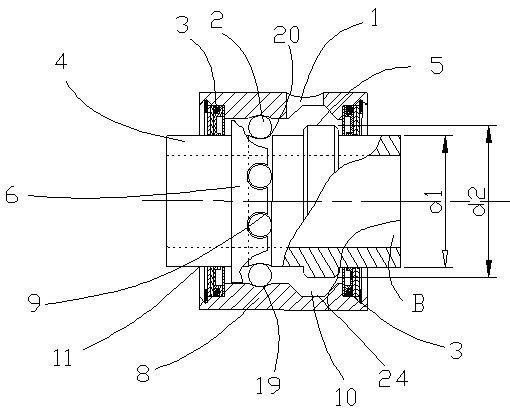
[0041] Example 1, such as figure 1 As shown, a self-excited oil mist jet lubricated high-speed bearing includes an outer ring 8 and an inner ring body 4, the inner ring body 4 is located inside the outer ring body 8, and the inner ring body 4 and the outer ring body 8 are coaxially arranged. The inner surface of the outer ring 8 is provided with an outer raceway 19 , and the outer surface of the inner ring body 4 is provided with an inner raceway 20 . The outer ring 8 and the inner ring body 4 are connected by a non-contact sealing assembly 3 to prevent oil from overflowing. An oil storage space 10 is provided on the inner wall of the outer ring 8, and the oil storage space 10 is a horizontal concave ring groove 24. The concave ring groove 24 communicates with the lubricating hole 1 provided on the outer ring 8. The outer surface of the inner ring body 4 is provided with a cage 6, and the cage 6 is evenly provided with semi-open pockets along the circumference. The side provi...
Embodiment 2
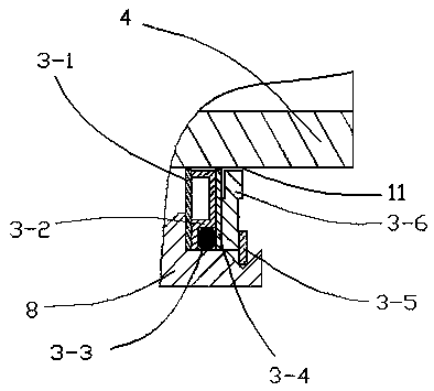
[0042] Example 2, such as figure 2 As shown, a self-excited oil mist spray lubricated high-speed bearing, the sealing assembly 3 includes an inner flat pad 3-1, an outer flat pad 3-4 and a special-shaped seal 3-2, an inner flat pad 3-1, an outer flat pad 3-1 A slit 11 is provided between the flat pad 3-4, the special-shaped seal 3-2 and the inner ring body, and does not affect the rotation of the outer body. The special-shaped seal 3-2 is located between the inner flat pad 3-1 and the outer flat pad 3-4, and an O-ring 3-3 is arranged between the special-shaped seal 3-2 and the outer ring sleeve 8 to ensure the sealing of the outer ring sleeve and Tightness between components 3. The outer end of the outer flat pad 3-4 is provided with a retaining ring 3-6, and the retaining ring 3-6 is clamped between the outer ring sleeve 8 and the inner ring body 4 through the snap spring 3-5. Due to an error during assembly, a structure similar to a groove is formed at the position adjace...
Embodiment 3
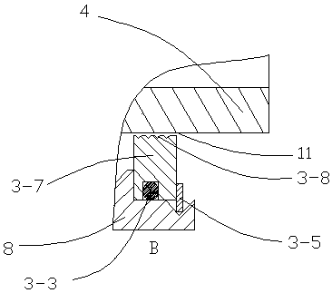
[0044] Example 3, such as image 3 As shown, a self-excited oil mist spray lubricated high-speed bearing, the sealing assembly 3 includes a gap sealing body 3-7, that is, a slit 11 is provided between the sealing body and the inner ring body 4, and does not affect the outer body rotation. The gap sealing body 3-7 is clamped between the outer ring casing 8 and the inner ring body 4 through the circlip 3-5, and an O-shaped sealing ring 3-3 is arranged between the gap sealing body 3-7 and the outer ring casing 8 to improve the gap sealing The tightness between the body 4 and the outer ring 8. An oil groove 3-8 is arranged on the adjacent surface of the gap sealing body 3-7 and the inner ring body 4, and the arrangement of the oil groove can effectively prevent oil from overflowing from the slit 11 between the sealing body and the inner ring body 4.
[0045] Other structures are the same as in Embodiment 1.
PUM
 Abstract
Description
Claims
Application Information
 - R&D
- Intellectual Property
- Life Sciences
- Materials
- Tech Scout
- Unparalleled Data Quality
- Higher Quality Content
- 60% Fewer Hallucinations
Browse by: Latest US Patents, China's latest patents, Technical Efficacy Thesaurus, Application Domain, Technology Topic, Popular Technical Reports.
© 2025 PatSnap. All rights reserved.Legal|Privacy policy|Modern Slavery Act Transparency Statement|Sitemap|About US| Contact US: help@patsnap.com


