Ultra-low nitrogen premixed gas burner and combustion method thereof

A gas burner, ultra-low nitrogen technology, applied in the direction of combustion methods, gas fuel burners, burners, etc., can solve the problems of limited use of burners, reduced combustion efficiency, etc., and achieve simple installation, stable combustion, and high combustion flame short effect

Pending Publication Date: 2019-12-13
ZHEJIANG UNIPOWER BOILER CO LTD
View PDF0 Cites 3 Cited by
  • Summary
  • Abstract
  • Description
  • Claims
  • Application Information

AI Technical Summary

Problems solved by technology

[0004] The purpose of the invention is to solve the problem of flue gas recirculation technology and fully premixed surface combustion technology in reducing NO X At the same time, the combustion efficiency will be reduced, an

Method used


Image

  • Ultra-low nitrogen premixed gas burner and combustion method thereof
  • Ultra-low nitrogen premixed gas burner and combustion method thereof
  • Ultra-low nitrogen premixed gas burner and combustion method thereof

Examples


Example Embodiment

[0033] Example one

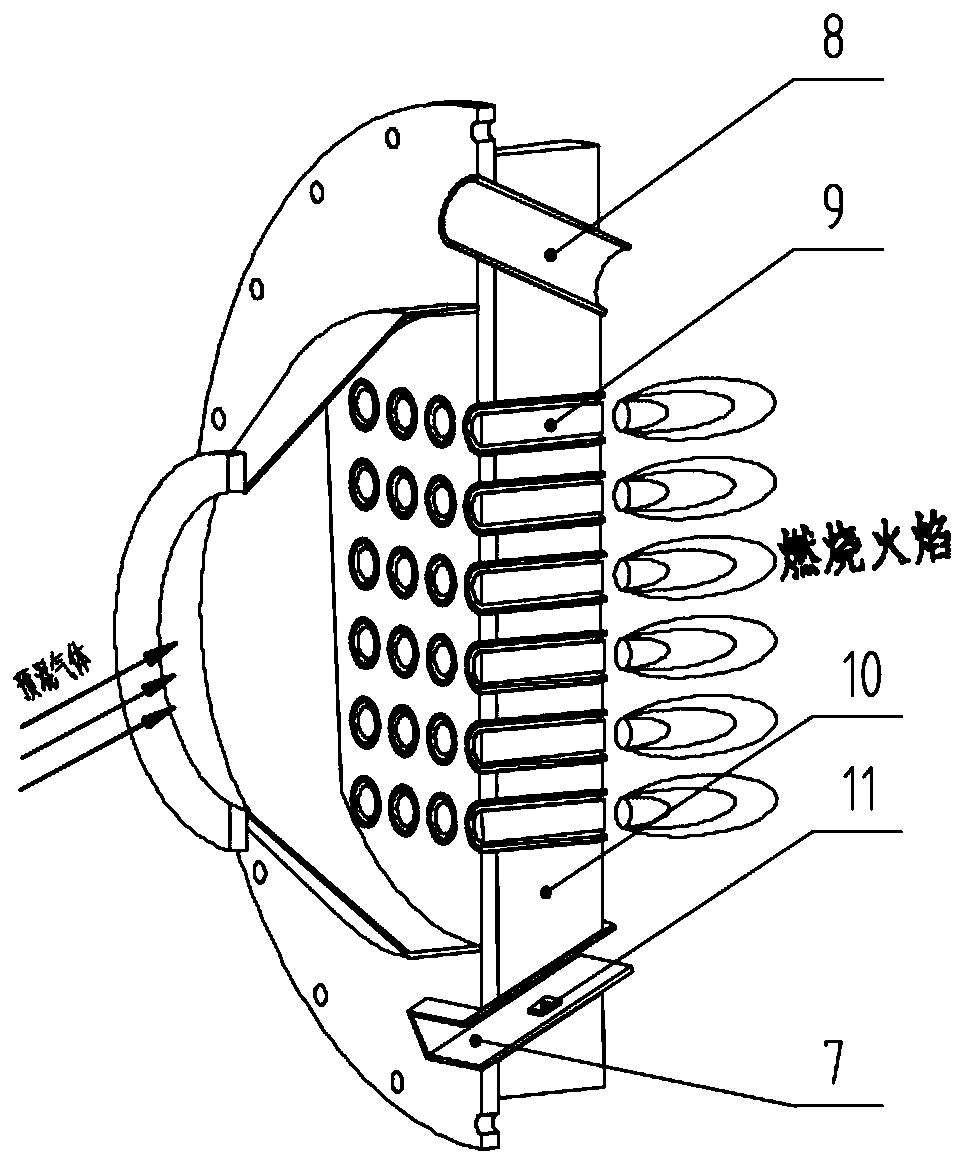
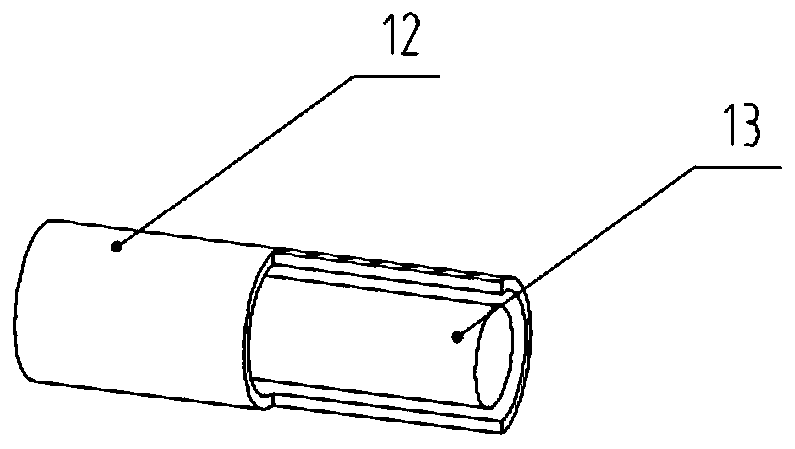
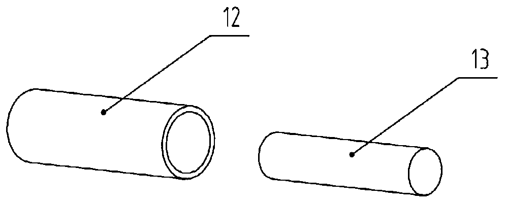
[0034] Such as Figure 1-7 As shown, this embodiment is an ultra-low nitrogen premixed gas burner, which includes several nozzles 9 arranged at the end of the burner, and the burner is connected to the furnace through the nozzles 9. The premixed gas in the burner is evenly split through the nozzle 9 and then enters the furnace. The premixed gas is ignited at the outlet end of the nozzle 9 and then ignited and burned in the furnace. The nozzle 9 includes a hollow shell 12 and a solid bluff body 13. The shell 12 is sleeved outside the bluff body 13, and a premixed gas flow channel is formed between the shell 12 and the bluff body 13. The casing 12 is a cylindrical shape with open ends, the bluff body 13 is cylindrical, and the length of the casing 12 is substantially the same as the length of the bluff body 13. In this embodiment, a large number of nozzles 9 are arranged at the end of the combustor, so that the premixed gas circulates in the channel of the no...

Example Embodiment

[0038] Example two

[0039] This embodiment also provides a combustion method for an ultra-low nitrogen premixed gas burner, which includes the following steps:

[0040] S1: Mix air and fuel gas into a premixed gas according to a set ratio, and pass the premixed gas into the distribution cavity;

[0041] S2, the premixed gas in the distribution chamber is evenly divided by several nozzles and then enters the furnace:

[0042] S3, the premixed gas is ignited at the nozzle outlet, so that the premixed gas is ignited and burned in the furnace.

[0043] Wherein, in step S1, the outlet end surface of the distribution cavity is provided with several nozzles with a certain length. In step S2, the premixed gas in the distribution cavity enters the furnace along the channel in the nozzle. In step S3, the premixed gas undergoes defiring combustion, with intense combustion, short combustion flame, stable combustion, high heat transfer efficiency, and low NOx content in the generated flue gas.


PUM


Abstract

The invention relates to the technical field of gas combustion devices, in particular to an ultra-low nitrogen premixed gas burner and a combustion method thereof. The ultra-low nitrogen premixed gasburner comprises a plurality of nozzles arranged at the tail end of the burner, and premixed gas in the burner enters a hearth after being uniformly distributed through the nozzles; after the premixedgas is ignited at the outlet ends of the nozzles, the premixed gas is subjected to blowoff combustion in the hearth; and the nozzles comprise hollow shells and solid blunt bodies, the blunt bodies are sleeved with the shells, and channels for premixed gas to flow are formed between the shells and the blunt bodies. According to the ultra-low nitrogen premixed gas burner, a full premixing combustion mode is adopted, and the plurality of nozzles are arranged at the tail end of the burner, so that the premixed gas flows in the nozzle channels and is blowoff combusted at the outlets of the nozzles, and low nitrogen oxide (NOx) emission is realized without reducing the combustion efficiency.

Description

technical field [0001] The invention relates to the technical field of gas combustion devices, in particular to an ultra-low nitrogen premixed gas burner and a combustion method thereof. Background technique [0002] Nitrogen oxides form acid rain, which is one of the components of air pollutants and one of the main components of smog. Beijing has promulgated a new "Emission Standard of Air Pollutants for Boilers", which stipulates that starting from April 1, 2017 , the NOx emission limit of all gas-fired boilers in use is 80mg / m 3 , new gas boiler nitrogen oxide NO X The emission limit is 30mg / m 3 , which puts forward the requirement of low nitrogen emission to the current combustion device. [0003] Gas combustion low-nitrogen combustion control technology mainly reduces the synthesis of nitrogen oxides by reducing the flame temperature. At present, there are three main types of gas combustion low-nitrogen combustion technologies on the market: flue gas recirculation t...

Claims


Application Information

Patent Timeline
IPC IPC(8): F23D14/02F23D14/46F23D14/48F23D14/62
CPCF23D14/02F23D14/46F23D14/48F23D14/62
Inventor 陈国良邱尔鹏郑国军
Owner ZHEJIANG UNIPOWER BOILER CO LTD
Why Eureka
Try Eureka