A system coupling sludge incinerator and heating unit

A technology for sludge incineration and heating units, which is applied in heating systems, incinerators, household heating, etc., and can solve the problems of reduced output demand of generator sets, safety impact of steam and water power, and reduction of sludge consumption.

Active Publication Date: 2021-05-18
CHINA ENERGY ENG GRP GUANGDONG ELECTRIC POWER DESIGN INST CO LTD
View PDF8 Cites 0 Cited by
  • Summary
  • Abstract
  • Description
  • Claims
  • Application Information

AI Technical Summary

Problems solved by technology

When connected to the reheating pipeline in the cold section, the steam volume of the sludge incinerator is limited by the area margin of the furnace reheater of the original boiler. If the margin is insufficient, the power safety of steam and water will be affected
Even if it is connected to the reheating pipe at the hot end, as the load of the raw pulverized coal boiler decreases, the proportion of the steam parameters of the sludge incinerator will increase, which will easily cause the strength and axial thrust of the high and medium pressure cylinders to exceed the standard
If the equipment capacity of the original unit is not allowed, it is necessary to reduce the output of the sludge incinerator to ensure the safety of the unit operation, so that the rated treatment capacity of the sludge cannot be guaranteed
[0005] To sum up, the existing system that couples the sludge incinerator with the thermal system of the original coal-fired unit can only be reduced by reducing the fuel volume of the sludge incinerator when the output demand of the generator set is reduced due to the influence of power grid dispatching. The ratio of coupled steam, in this way, also reduces the sludge consumption, that is, the sludge consumption is indirectly affected by the load of the original coal-fired unit
Therefore, the existing technology of coupling the sludge incinerator with the thermal system of the original coal-fired unit has certain limitations.

Method used


Image

  • A system coupling sludge incinerator and heating unit

Examples


Embodiment Construction

[0018] The technical solutions in the embodiments of the present invention will be clearly and completely described below in conjunction with the accompanying drawings in the embodiments of the present invention. Obviously, the described embodiments are only some, not all, embodiments of the present invention. Based on the embodiments of the present invention, all other embodiments obtained by persons of ordinary skill in the art without creative efforts fall within the protection scope of the present invention.

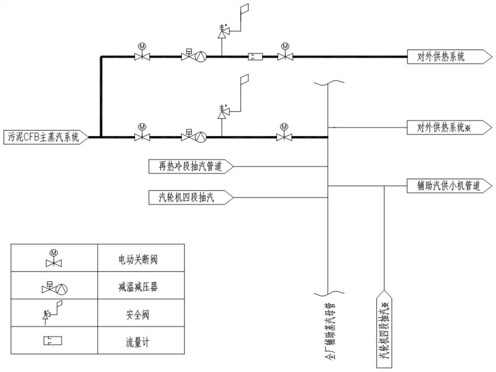
[0019] See figure 1 , the embodiment of the present invention provides a system for coupling the sludge incinerator and the heating unit, including the main steam system of the sludge incinerator, the external heating system, and the auxiliary steam system of the original unit;

[0020] The steam outlet of the main steam system of the sludge incinerator is respectively connected with the first steam inlet of the external heating system and the steam inlet of the auxi...


PUM


Abstract

The invention discloses a system for coupling a sludge incinerator to a heating unit, comprising a main steam system of the sludge incinerator, an external heating system, and an auxiliary steam system of the original unit; the steam outlet of the main steam system of the sludge incinerator They are respectively connected to the first steam inlet of the external heating system and the steam inlet of the auxiliary steam system of the original unit, and the steam outlet of the auxiliary steam system of the original unit is connected to the second steam inlet of the external heating system; The main steam system of the sludge incinerator is used to transport steam to the external heating system according to the preset heating steam consumption. By coupling the sludge incinerator with the heating system of the coal-fired unit, the present invention can make the sludge incinerator run at a stable load for a long time, thereby ensuring the rated sludge consumption, and realizing sludge incineration and external supply Hot as well as hot.

Description

technical field [0001] The invention relates to the technical field of energy saving and emission reduction, in particular to a system coupling a sludge incinerator and a heating unit. Background technique [0002] Sludge incineration is currently the mainstream sludge treatment solution. The sludge incinerator is mainly based on the fluidized bed (CFB or BFB). Due to the limitation of the calorific value of the sludge itself and the influence of the furnace type, the main steam parameters at the outlet of the sludge incinerator are generally lower than those of the medium-sized coal-fired units. Therefore, it is generally not recommended to install a separate steam turbine power generation system for the sludge incinerator. The conventional technical solution is to couple the main steam at the outlet of the sludge incinerator with the thermal system of the original coal-fired unit of the power plant. The hot steam enters the middle and low pressure cylinders of the steam ...

Claims


Application Information

Patent Timeline
Patent Type & Authority Patents(China)
IPC IPC(8): F24D12/02F24D19/10F23G5/46F23G7/00F01K17/02
CPCF01K17/02F23G5/46F23G7/001F24D12/02F24D19/1003F24D2200/16Y02B30/00Y02E20/12
Inventor 石韬吴阿峰李伟科霍沛强樊晓茹张翔宇韩卫冬王钦
Owner CHINA ENERGY ENG GRP GUANGDONG ELECTRIC POWER DESIGN INST CO LTD
Why Eureka
Try Eureka