
Self-adaptive aberration correction image scanning microscopic imaging method and device

A technology for aberration correction and microscopic imaging, applied in microscopes, measuring devices, and material analysis through optical means, can solve the problem of refractive index mismatch, reduce the resolution of image scanning microscopic imaging, and affect the effect of pixel redistribution and other issues to achieve real-time correction, improve contrast and resolution, and achieve adaptive aberration correction

Active Publication Date: 2019-12-13
哈工大机器人(中山)无人装备与人工智能研究院
View PDF6 Cites 5 Cited by
  • Summary
  • Abstract
  • Description
  • Claims
  • Application Information

AI Technical Summary

Problems solved by technology

However, when using the image scanning microscopy imaging method to measure the depth of the sample, due to the mismatch of the refractive index, the effect of pixel redistribution is affected, and the resolution of the image scanning microscopy imaging is reduced.

Method used


Image

  • Self-adaptive aberration correction image scanning microscopic imaging method and device
  • Self-adaptive aberration correction image scanning microscopic imaging method and device
  • Self-adaptive aberration correction image scanning microscopic imaging method and device

Examples


Embodiment Construction

[0027] The implementation examples of the present invention will be described in detail below in conjunction with the accompanying drawings.

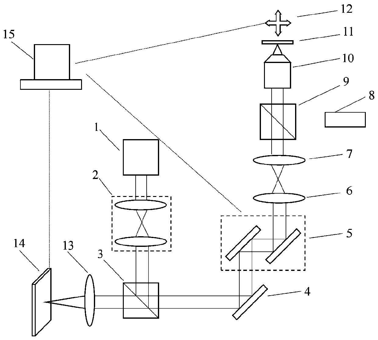
[0028] A schematic diagram of an embodiment of an adaptive aberration-corrected image scanning microscopy imaging method and device is shown in figure 1 shown. The laser beam emitted by the laser 1 is shaped and expanded by the beam shaping and expanding system 2 , and then reflected by the first beam splitter 3 and enters the aberration correction system 4 . The wavefront of the incident light field is phase-modulated by a computer-controlled aberration correction system. The modulated laser light passes through the two-dimensional scanning galvanometer 5 , the scanning lens 6 , and the tube mirror 7 sequentially, passes through the second beam splitter 9 , and is focused by the objective lens 10 to detect points on the sample 11 . Three-dimensional measurement is realized through the movement of the three-dimensional translation pla...


PUM


Abstract

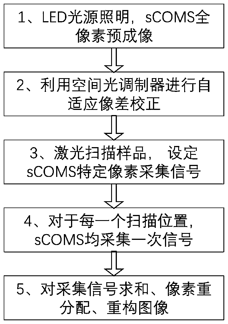
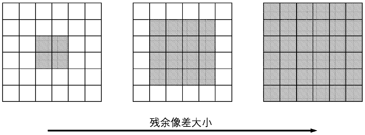
The invention relates to a self-adaptive aberration correction image scanning microscopic imaging method and device and belongs to the field of optical microscopic measurement. According to the self-adaptive aberration correction image scanning microscopic imaging method and device of the invention, an aberration correction system is introduced into an image scanning microscopic imaging method soas to carry out adaptive aberration correction. Before correction, a sCOMS is directly utilized to perform full-pixel pre-imaging, and a full-pixel image is utilized to form an adaptive aberration correction evaluation function. An image evaluation function is tested in real time in a correction process, and a computer is used for controlling the aberration correction system to carry out self-adaptive aberration correction. This process does not need scanning, and is quick and simple. And parameters of a pixel redistribution process are reset on the basis of the change of the evaluation function in an aberration correction process, so that the pixel redistribution process is optimized. The number of the effective pixels of the sCMOS camera in a laser scanning microscopy process is set according to residual aberration. With the method adopted, the aberration of the image scanning microscopic imaging system can be effectively corrected, the effectiveness of the pixel redistribution process can be improved, and the improvement of image scanning imaging resolution can be achieved to the greatest extent.

Description

technical field [0001] The invention belongs to the field of optical microscopic measurement, and mainly relates to an ultra-precise non-contact measurement method for measuring three-dimensional microstructures in micro devices, surface topography and biological samples. Background technique [0002] The resolution of conventional optical microscopy imaging techniques is limited by the diffraction limit. In response to this problem, scientists have proposed many microscopic imaging methods to improve imaging resolution. The confocal scanning microscope uses point detection, scans the sample through a focused spot, and uses an optical pinhole for apodization, which effectively improves the imaging resolution. However, due to the existence of pinholes, it also brings about the problem of lowering the imaging signal-to-noise ratio. Structured light lighting technology can improve the resolution by modulating the illumination light. However, the structured light microscopy i...

Claims


Application Information

Patent Timeline
IPC IPC(8): G01N21/84G01N21/01G02B21/00G02B21/36
CPCG01N21/84G01N21/01G02B21/0072G02B21/365G01N2021/0112G01N2201/127
Inventor 王伟波吴必伟王绍凯谭久彬
Owner 哈工大机器人(中山)无人装备与人工智能研究院
Learn More