
Test platform for driven grinding mode of steel rail

A technology for testing platforms and rails, which is applied to measuring devices, instruments, and mechanical devices, etc., and can solve the problems that passive grinding wheels cannot be independently localized

Inactive Publication Date: 2019-12-17
HENAN UNIVERSITY OF TECHNOLOGY
View PDF6 Cites 5 Cited by
  • Summary
  • Abstract
  • Description
  • Claims
  • Application Information

AI Technical Summary

Problems solved by technology

[0004] However, at this stage, rail passive grinding vehicles mainly rely on imports in China, and passive grinding wheels cannot be fully localized. Most commodities still rely on foreign imports. The domestic method and principle of passive grinding of rails are still in the exploration and exploration stage. The research and development and product upgrading of passive grinding wheels for rails in the abrasive tool industry are also being carried out simultaneously
However, at present, there are few test platforms at home and abroad that can simulate passive grinding methods of rails. The impact of the grinding wheel on grinding, etc., to simulate and test various parameters in the process of passive grinding of rails, and to evaluate the practical performance of passive grinding wheels for rails, it is urgent to develop a test platform for passive grinding of rails, so as to promote the passive grinding of domestic machinery industry. The research and development of vehicles, the research and development of passive grinding wheels and product upgrades in the abrasives industry, formulate appropriate passive grinding process parameters and suitable passive grinding products suitable for domestic lines, ensure the effect of passive grinding of rails, and safeguard national interests and The development of independent industrial economy

Method used


Image

  • Test platform for driven grinding mode of steel rail
  • Test platform for driven grinding mode of steel rail
  • Test platform for driven grinding mode of steel rail

Examples


Embodiment Construction

[0034] The present invention will be further described below in conjunction with embodiment (accompanying drawing):

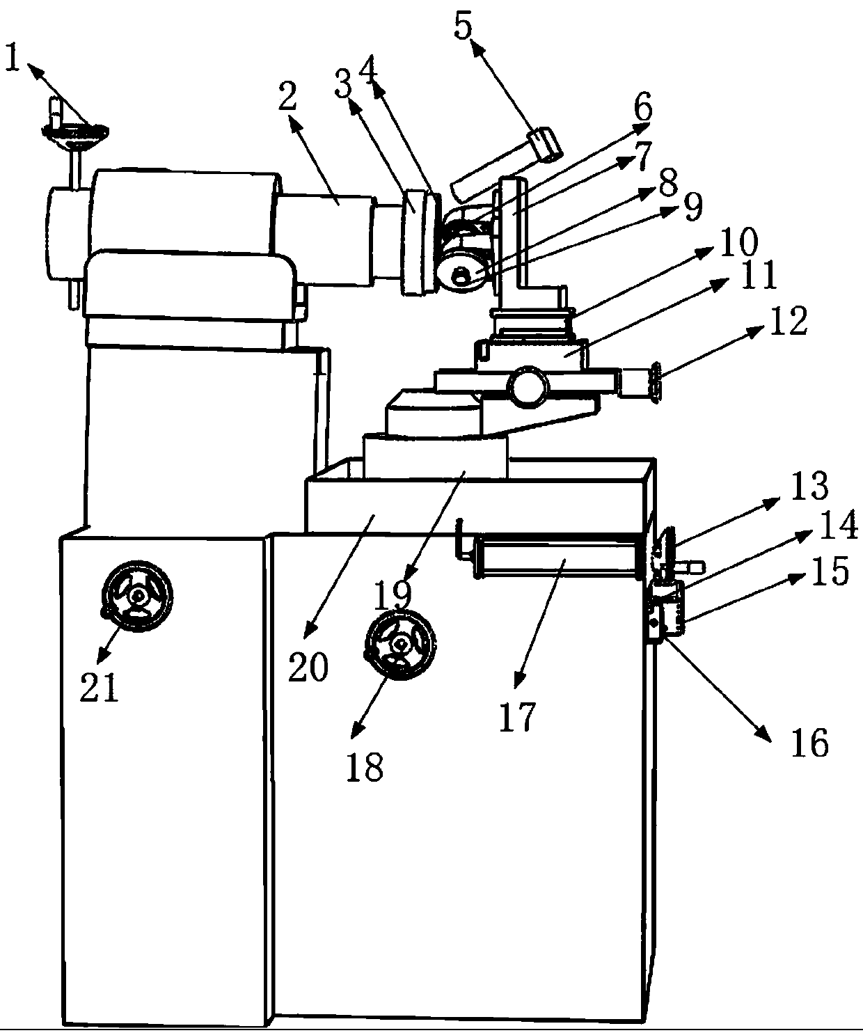
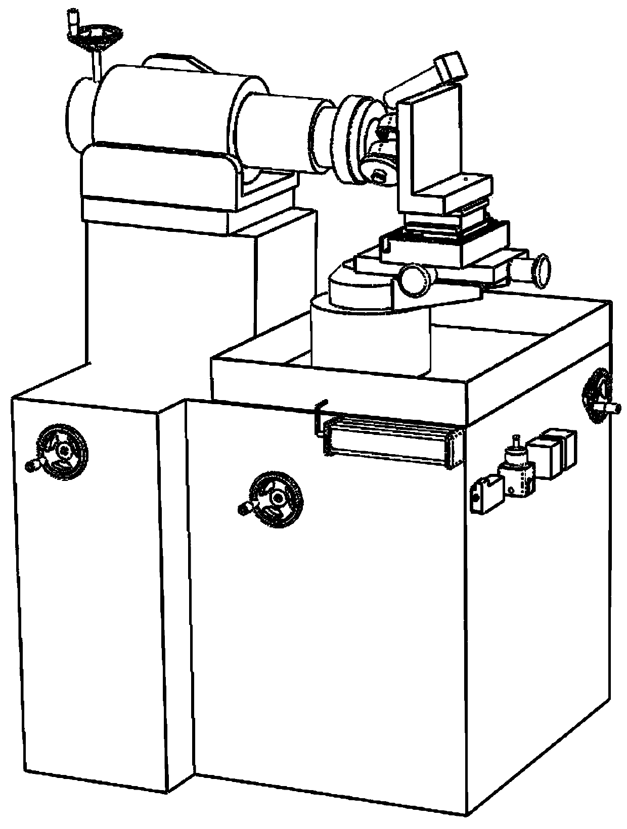
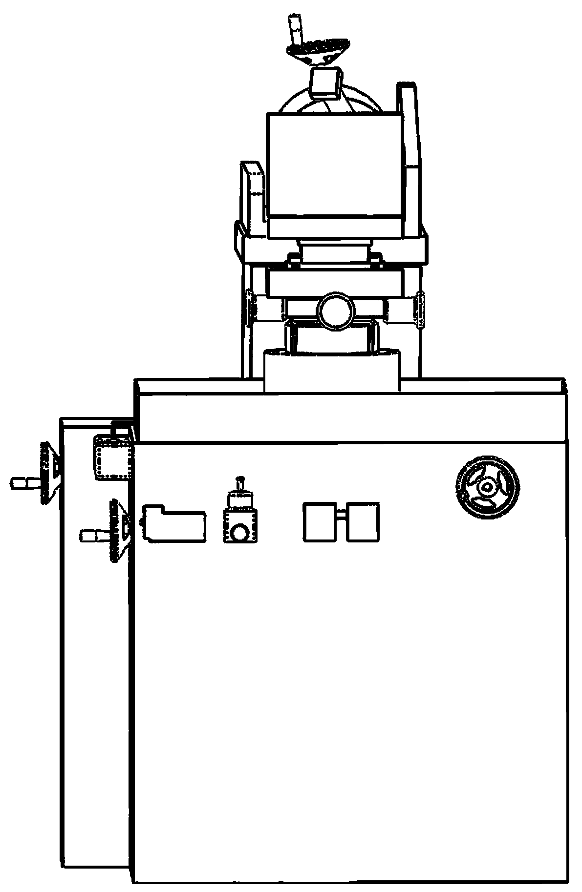
[0035] Such as figure 1 As shown, the test platform of the rail passive grinding mode of the present invention comprises a motor 1 installed on the machine tool control cabinet through height adjustment and front and rear displacement mechanisms, and a rail disc sample 4 installed on the front end of the motor spindle; The passive grinding wheel 8 installed on the machine tool workbench in such a way that the sample is relatively arranged, the passive grinding wheel 8 is installed on one end of the bearing shaft 9, and the bearing shaft 9 is fixed on one side of the L-shaped supporting steel plate 7 through the bearing with seat 6; The L-shaped support steel plate 7 installs the base fixed platform 11 through the three-dimensional mechanical sensor 10, and the base fixed platform 11 is installed on the high and low lifting platform 19 through the horizontal ang...


PUM


Abstract

The invention discloses a test platform for a driven grinding mode of a steel rail. The test platform is characterized by comprising a motor (2) mounted on a machine tool control cabinet through a height adjusting and front-back displacement mechanism, a steel rail disc sample (4) mounted at the front end of a main shaft of the motor, a driven grinding wheel (8) mounted on a machine tool workbench, opposite to the steel rail disc sample and at one end of a bearing shaft (9), the bearing shaft (9) fixed to one side of an L-shaped supporting steel plate (7) through a mounted bearing (6), the L-shaped supporting steel plate (7) mounted on a base fixing table (11) through a three-dimensional mechanical sensor (10), the base fixing table (11) mounted on a lifting platform (19) through a horizontal angle adjusting mechanism, the lifting platform (19) mounted on the machine tool workbench via the height adjusting and front-back displacement mechanism, and an infrared thermometer (5), capableof synchronously measuring and recording the grinding temperature during grinding, mounted at the top of the L-shaped supporting steel plate (7).

Description

technical field [0001] The invention relates to a test platform for passive grinding of rails. Background technique [0002] Railway is the main artery of the national economy, key infrastructure and major livelihood projects, and is one of the main modes of transportation in the comprehensive transportation system. As the core component of the railway system, while the rail provides guidance to the rolling stock, it is prone to various damages and damages on the surface and inside due to the impact of complex and variable loads from the vertical, horizontal and longitudinal loads during the service process. Defects such as corrugation, cracks, peeling, crushing, pitting, and fat edges, etc. Due to the cumbersome operation and high cost of the rail changing process, rail grinding and repair has become a universal method recognized in the world to remove surface damage and defects and improve the wheel-rail matching relationship. It can effectively suppress rolling contact f...

Claims


Application Information

Patent Timeline
IPC IPC(8): G01D21/02G01N19/06
CPCG01D21/02G01N19/06
Inventor 邹文俊刘鹏展李焕峰李端韩平袁天顺简亚溜彭进
Owner HENAN UNIVERSITY OF TECHNOLOGY
Features
  • Generate Ideas
  • Intellectual Property
  • Life Sciences
  • Materials
  • Tech Scout
  • Unparalleled Data Quality
  • Higher Quality Content
  • 60% Fewer Hallucinations
Learn More