Device and method for testing oscillation performance of cooling oil in internal combustion engine piston

A test device, oil vibration technology, applied in the direction of internal combustion engine testing, measuring devices, testing of mechanical components, etc., can solve the problem of not being able to observe the cooling oil vibration shape and flow characteristics, and not being able to better support quantitative design of piston cooling, and not being able to quantify Accurately judge the vibration speed of the cooling oil and the vibration cooling capacity, etc., to achieve the effect of easy replacement, strong versatility, and simple structure of the device

Inactive Publication Date: 2019-12-17
HUAZHONG UNIV OF SCI & TECH
View PDF7 Cites 5 Cited by
  • Summary
  • Abstract
  • Description
  • Claims
  • Application Information

AI Technical Summary

Problems solved by technology

[0006] But the experimental device of above-mentioned patent all is the simulation experiment (mainly used in internal-combustion engine for vehicles) of injecting type piston oscillation cooling, is not suitable for the piston oscillation cooling of press-in type (mainly used in large-scale internal-combustion engine of ship), and The oscillating shape and flow characteristics of the cooling oil in the piston oscillating cooling chamber cannot be observed, so the oscillating speed and oscillating cooling capacity of the cooling oil cannot be judged quantitatively, so the quantitative design of the piston cooling capacity cannot be well supported

Method used


Image

  • Device and method for testing oscillation performance of cooling oil in internal combustion engine piston
  • Device and method for testing oscillation performance of cooling oil in internal combustion engine piston
  • Device and method for testing oscillation performance of cooling oil in internal combustion engine piston

Examples


Embodiment Construction

[0032] In order to make the object, technical solution and advantages of the present invention clearer, the present invention will be further described in detail below in conjunction with the accompanying drawings and embodiments. It should be understood that the specific embodiments described here are only used to explain the present invention, not to limit the present invention. In addition, the technical features involved in the various embodiments of the present invention described below can be combined with each other as long as they do not constitute a conflict with each other.

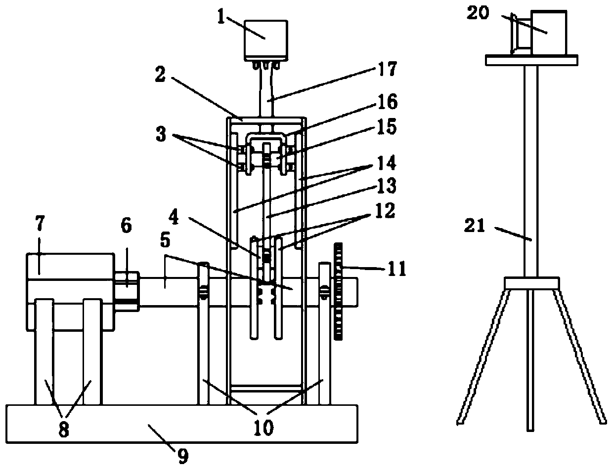
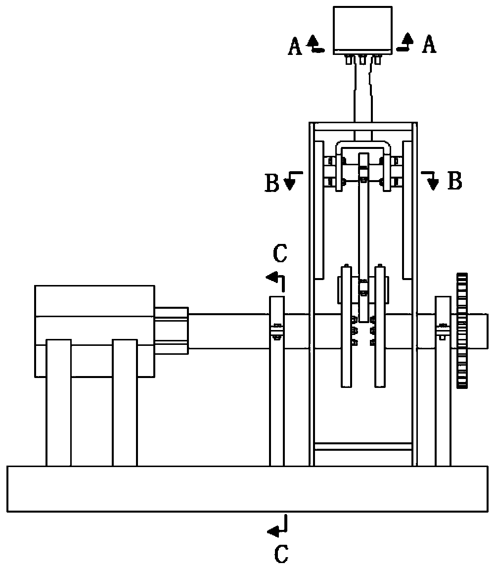
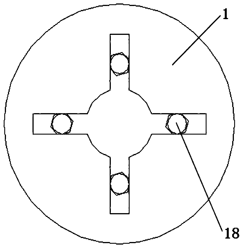
[0033] An embodiment of the present invention provides a device for testing the vibration performance of the cooling oil in the piston of an internal combustion engine, such as figure 1 and figure 2 As shown, it includes a support mechanism, a visualization piston 1, a guide mechanism, a crank linkage mechanism, a power control mechanism and an observation camera 20, wherein:

[0034] Describ...


PUM


Abstract

The invention belongs to the field of internal combustion engines, and particularly discloses a device and a method for testing oscillation performance of cooling oil in an internal combustion enginepiston. The device comprises a supporting mechanism, a guiding mechanism, a crank connecting rod mechanism, a power control mechanism, a visual piston and an observation camera, wherein the supportingmechanism comprises a supporting frame, a rotating shaft bracket, a motor bracket and a pedestal; the guiding mechanism comprises a connecting link, a crosshead, a sliding rail and a sliding block, the crosshead is connected with the visual piston by means of the connecting link, the sliding rail is installed in the supporting frame, one side of the sliding block is fixed on the crosshead, and the other side of the sliding block is installed in the sliding rail; the crank-link mechanism comprises a connecting rod, a crank arm and a crank pin, one end of the connecting rod is fixed on the crosshead, and the other end is connected with the crank arm by means of the crank pin; and the power control mechanism drives the piston to reciprocate by means of the crank connecting rod mechanism andthe guiding mechanism, and the observation camera carries out shooting. The device is simple in structure, easy to maintain, high in universality and capable of precisely observing the oscillation performance of the cooling oil in the piston.

Description

technical field [0001] The invention belongs to the field of internal combustion engines, and more specifically relates to a device and method for testing the vibration performance of cooling oil in pistons of internal combustion engines. Background technique [0002] Internal combustion engines have been widely used in the power industry due to their low operating costs, flexible usage scenarios, and high thermal efficiency. With the expansion of the application range of internal combustion engines and the increase in power requirements, the degree of strengthening of internal combustion engines continues to increase. [0003] As one of the core components of the internal combustion engine, the piston not only needs to be in direct contact with the gas with a temperature as high as 2500°C to be periodically heated during the actual working process of the internal combustion engine, but also bears a large mechanical load under the action of ultra-high explosion pressure. In...

Claims


Application Information

Patent Timeline
Patent Type & Authority Applications(China)
IPC IPC(8): G01M15/04G01M13/00
CPCG01M13/00G01M15/04
Inventor 成晓北潘福敏王兆文李梅田帆
Owner HUAZHONG UNIV OF SCI & TECH
Why Eureka
Try Eureka