Transformer and inductance magnetic integration structure

A magnetic integration and transformer technology, which is applied in transformer/inductor cores, transformer/inductor parts, transformers, etc., can solve the problems of low utilization rate of magnetic cores, large magnetic flux in the middle column of magnetic cores, and large losses , to achieve the effect of flexible core structure, low core loss and high power density

Inactive Publication Date: 2019-12-17
NANJING UNIV OF AERONAUTICS & ASTRONAUTICS
View PDF6 Cites 10 Cited by
  • Summary
  • Abstract
  • Description
  • Claims
  • Application Information

AI Technical Summary

Problems solved by technology

However, this method relies on the core column for decoupling, the utilization rate of the core is not high, and

Method used


Image

  • Transformer and inductance magnetic integration structure
  • Transformer and inductance magnetic integration structure
  • Transformer and inductance magnetic integration structure

Examples


Embodiment Construction

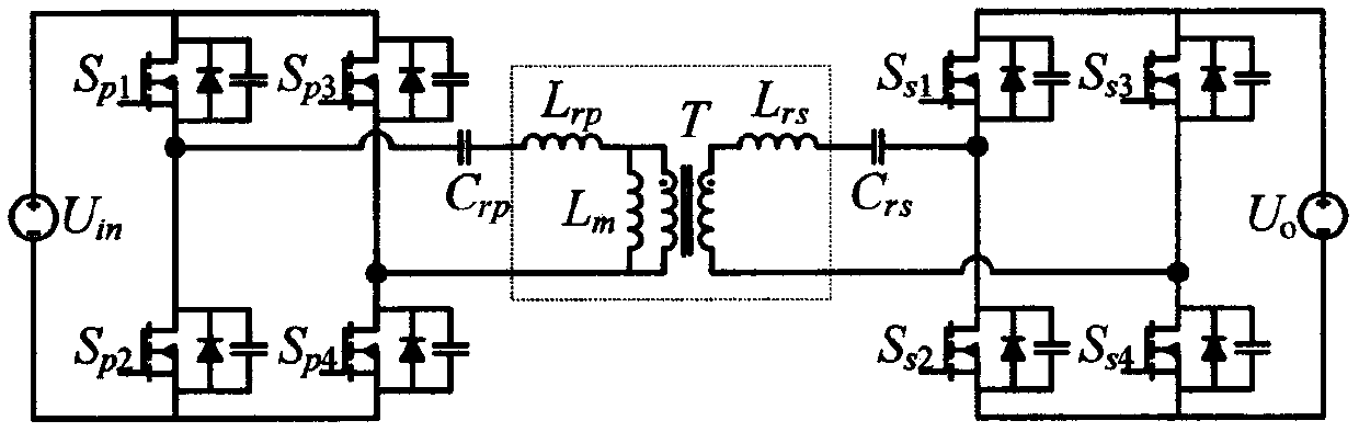
[0038] attached figure 1 It is the schematic diagram of the existing bidirectional CLLC resonant converter before integration, which includes a transformer and two inductors. In order to reduce the size and improve efficiency, the present invention uses magnetic integration technology to simultaneously integrate the transformer and two inductors into one magnetic core. The technical solution of the present invention will be described in detail below in conjunction with the accompanying drawings.

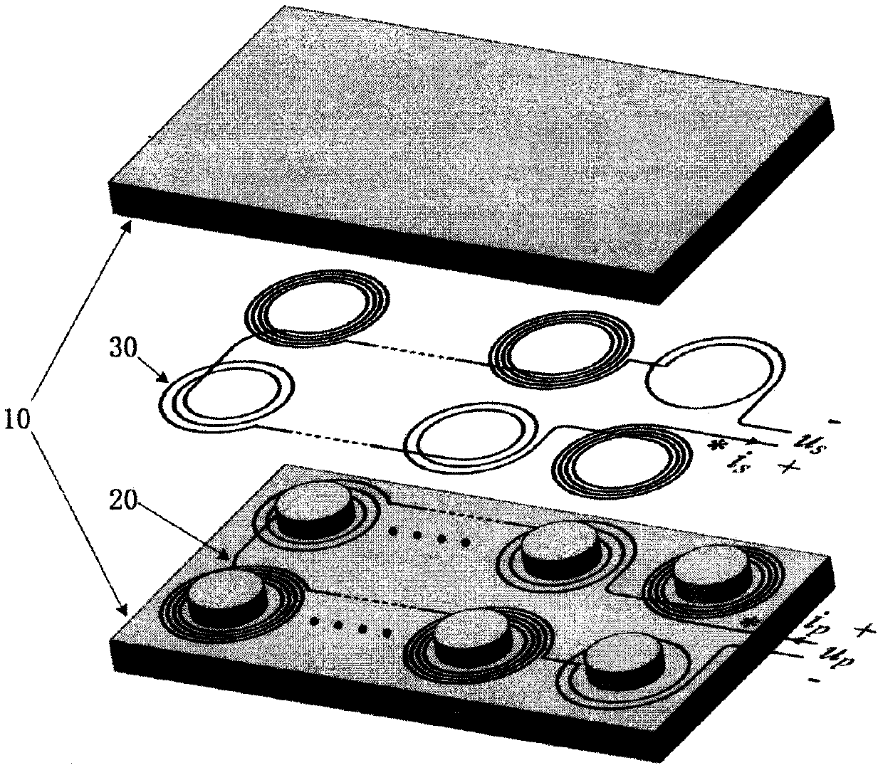
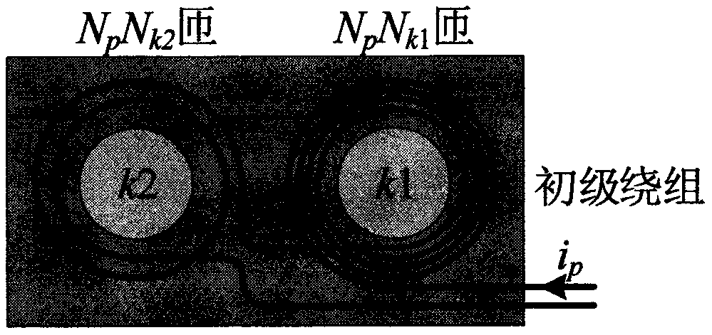
[0039] Such as figure 2 As shown, the integrated structure of a transformer and an inductance magnetic is composed of a magnetic core (10), a primary winding (20), and a secondary winding (30), wherein a part of the primary winding and / or a part of the secondary winding are wound There are a total of 2X (X≥2) columns, and a total of Y (≥0) magnetic columns without winding windings. Every two magnetic columns wound with part of the primary winding and / or part of the secondary windi...


PUM


Abstract

The invention discloses a transformer and an inductance magnetic integration structure, and belongs to the technical field of power electronics. The transformer inductance magnetic integration structure is composed of a pair of magnetic cores including at least four magnetic columns, a primary winding and a secondary winding. One transformer and two inductors can be integrated in one magnetic core, flexible configuration of the winding structure can also be realized, any transformer turn ratio, any excitation inductance and leakage inductance ratio can be realized and the magnetic core loss can also be reduced and the efficiency can be improved. Meanwhile, the integrated structure greatly reduces the volume and the weight of power magnetic parts so as to be helpful to improve the power density of the converter. The structure is particularly suitable for various applications such as bidirectional CLLC resonant converters and the like where transformers and inductors are used for high-frequency, high-efficiency and high-power density power conversion.

Description

technical field [0001] The invention relates to a transformer and an inductive magnetic integrated structure, which belongs to the technical field of power electronics. Background technique [0002] With the development of modern power electronics technology and the birth of high frequency switching devices such as SiC and GaN, high frequency, integration and modularization have become the development trend of switching power supplies. Facts have shown that increasing the switching frequency can reduce the size of the device, improve power density and reliability, and reduce switching noise. Resonant converters are favored by the industry for their excellent soft switching, high efficiency, and high power density, and are widely used in server power supplies, new energy electric vehicle charging piles, and other occasions. Among them, due to the symmetry of its structure, the CLLC resonant converter can realize bidirectional power transmission, and can realize soft switchin...

Claims


Application Information

Patent Timeline
IPC IPC(8): H01F27/24H01F27/30H01F30/06H01F37/00H02M1/00
CPCH01F27/24H01F27/306H01F30/06H01F37/00H02M1/00H02M1/0064
Inventor 吴红飞汤欣喜花文敏刘越
Owner NANJING UNIV OF AERONAUTICS & ASTRONAUTICS
Why Eureka
Try Eureka