Visual-system-based equipment for placing valves into trays automatically

A vision system and valve technology, applied in metal processing, etc., can solve the problems of slow production efficiency, huge equipment, unfavorable enterprise development, etc., and achieve the effect of ensuring high-efficiency completion of work

Pending Publication Date: 2019-12-20
CHONGQING ELECTROMECHANICAL VOCATIONAL INST
View PDF1 Cites 8 Cited by
  • Summary
  • Abstract
  • Description
  • Claims
  • Application Information

AI Technical Summary

Problems solved by technology

[0022] With the continuous development of science and technology and social production, higher and higher requirements are put forward for the performance, quality, productivity and cost of mechanical products in the processing and manufacturing industry, and the realization of mechanical processing automation is one of the important technical measures for the above requirements , it can not only improve the quality and productivity of parts, reduce production costs, but also improve the working conditions of workers, but the use of this automatic, high-efficiency equipment requires a large initial investment and a long production cycle, only in mass production Under certain conditions, there will be significant economic benefits, and the enterprise will have a certain development; and now the valves are basically produced by manual materials, and the valves are placed neatly one by one with special containers, which is inefficient and labor intensive. The labor utilization rate is low, or the method of processing assembly line is adopted, the equipment is huge, the area is large, and the cost is high, which is not conducive to the development of the enterprise
[0023] The patent No. 201621178132.4 is "a valve automatic loading and loading mechanism". The material holding mechanism needs to manually position and place the trays each time. After each round of trays is used up, it is necessary to stop the equipment and reposition the trays. The equipment cannot be kept running, and the production efficiency is relatively slow.

Method used


Image

  • Visual-system-based equipment for placing valves into trays automatically
  • Visual-system-based equipment for placing valves into trays automatically
  • Visual-system-based equipment for placing valves into trays automatically

Examples


Embodiment Construction

[0053] In order to make the technical means, creative features, objectives and effects achieved by the present invention easy to understand, the present invention will be further described below in conjunction with specific embodiments.

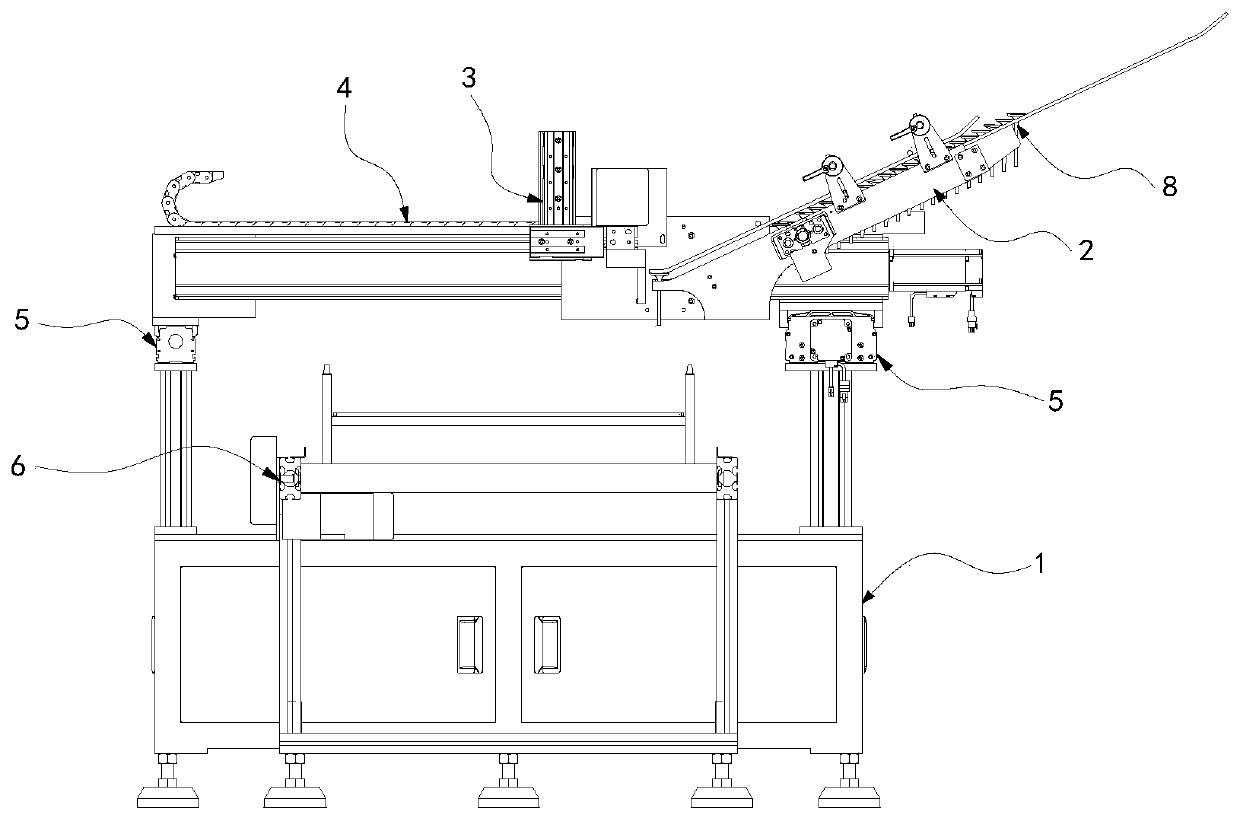
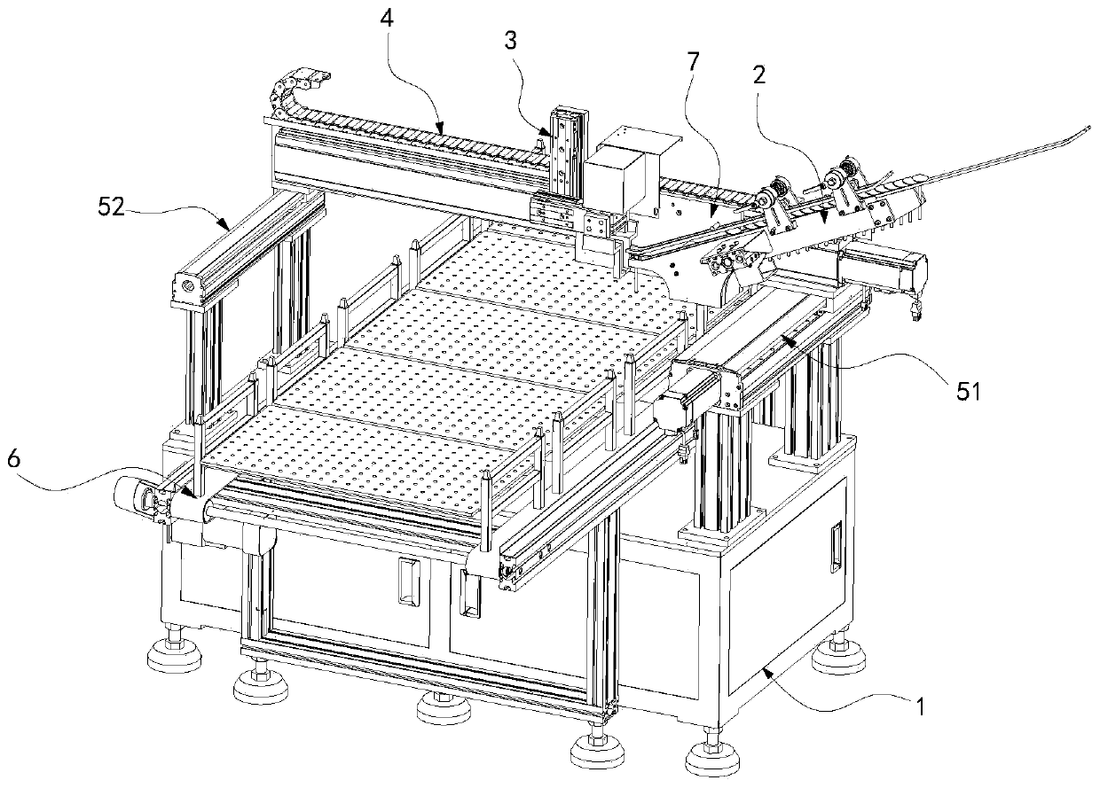
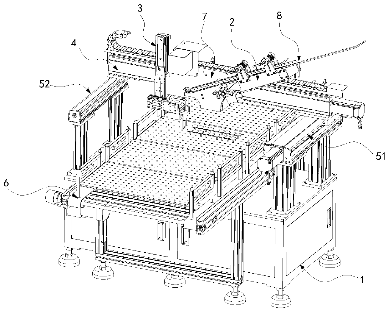
[0054] Such as figure 1 , figure 2 , image 3 The shown automatic valve swinging device based on the vision system includes an electric control cabinet 1, a feeding mechanism 2, a material insertion mechanism 3, a module traverse mechanism 4, a module longitudinal mechanism 5 and a tray transmission mechanism 6. The module wale mechanism 5 includes an active guide rail group 51 and a driven guide rail group 52 arranged in parallel on the electric control cabinet, and the tray transmission mechanism 6 is erected above the electric control cabinet 1 along the walking direction of the module wale mechanism 5 , and between the active guide rail group 51 and the driven guide rail group 52 arranged side by side. 3 is movably installed on the mo...


PUM


Abstract

The invention relates to the field of automatic production equipment, in particular to visual-system-based equipment for placing valves into trays automatically. The visual-system-based equipment comprises an electric control cabinet, a material feeding mechanism, a material insert mechanism, a module horizontal traveling mechanism, a module longitudinal traveling mechanism and a material tray transmission mechanism, wherein the module longitudinal traveling mechanism comprises a driving guide rail set and a driven guide rail set which are parallelly arranged on the electric control cabinet, the material tray transmission mechanism is arranged above the electric control cabinet in an erected manner in the traveling direction of the module longitudinal traveling mechanism, the module horizontal traveling mechanism is arranged on the driving guide rail set and the driven guide rail set in an erected manner, the material feeding mechanism and the material insert mechanism are movably installed on the module horizontal traveling mechanism through a sliding plate, and the material feeding direction of the material feeding mechanism is inclined to the horizontal traveling direction of the material insert mechanism. The visual-system-based equipment for placing the valves into the trays automatically has the beneficial effects that the more accurate function of placing the valves intothe trays is realized in combination with a visual system, different from valve material tray positioning installation in the prior art and in combination with an assembly line type transmission method, the purpose of placing the valves into the trays is achieved more efficiently under an equipment continuous running state, operations are more flexible, and the work intensity is lowered more.

Description

technical field [0001] The invention relates to the field of automatic material-holding equipment in production workshops, and in particular to an automatic plate-setting device for valves based on a vision system, which is used for unloading after valve processing and neatly arranging the valves. Background technique [0002] A typical machine vision system can be divided into: image acquisition part, image processing part and motion control part. The PC-based vision system consists of figure 1 The parts shown are: [0003] ①Industrial camera and industrial lens - this part belongs to the imaging device. The usual vision system is composed of one or more sets of such imaging systems. If there are multiple cameras, the image data may be obtained by switching the image card, or it may be The data of multiple camera channels is acquired simultaneously by synchronization control. According to the needs of the application, the camera may output standard monochrome video (RS-1...

Claims


Application Information

Patent Timeline
Patent Type & Authority Applications(China)
IPC IPC(8): B23Q7/04B23Q7/00
CPCB23Q7/00B23Q7/04
Inventor 张华宋辉杨川陈华余衡罗文赵志雄舒子豪韩鑫朱文杰胡炜杰曾洪力涂毅
Owner CHONGQING ELECTROMECHANICAL VOCATIONAL INST
Why Eureka
Try Eureka