Steering-by-wire system and control method thereof

A technology of steer-by-wire and steering column, which is applied to steering mechanism, electric steering mechanism, power steering mechanism, etc., which can solve the problems of high energy consumption and slow response speed, and achieve the effect of safe steering and high safety

Active Publication Date: 2019-12-20
TSINGHUA UNIV
View PDF9 Cites 3 Cited by
  • Summary
  • Abstract
  • Description
  • Claims
  • Application Information

AI Technical Summary

Problems solved by technology

[0003] The purpose of the embodiments of the present application is to provide a steer-by-wire system and its control method to solve the problems of large energy consumption and slow response speed in the hydraulic system used in existing commercial vehicles

Method used


Image

  • Steering-by-wire system and control method thereof
  • Steering-by-wire system and control method thereof
  • Steering-by-wire system and control method thereof

Examples


no. 1 example

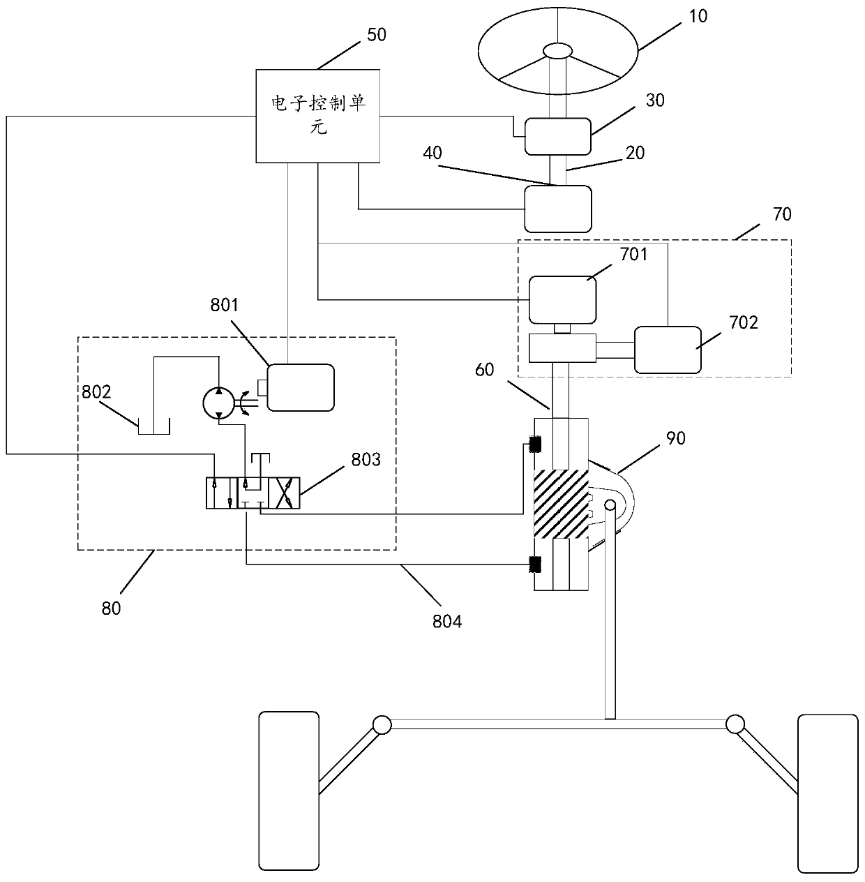
[0040] Such as figure 1 As shown, the present application provides a steer-by-wire system, which includes a steering wheel 10, a first steering column 20, a first torque angle sensor 30, a road feeling feedback unit 40, an electronic control unit 50, and a second steering column 60 , motor assist unit 70, hydraulic assist unit 80 and recirculating ball hydraulic power steering 90, the motor assist unit 70 includes a first motor steering assist unit 701 and a second motor steering assist unit 702, the hydraulic assist unit 80 includes an electro-hydraulic Pump 801, oil tank 802, electromagnetic reversing valve 803 and oil pipe 804; the steering wheel 10 is connected to the torque input end of the first steering column 20, and the first torque angle sensor 30 is sleeved on the first steering column 20, the road The sense feedback unit 40 is connected to the torque output end of the first steering column 20, the first motor steering assist unit 701 and the second motor steering a...

no. 2 example

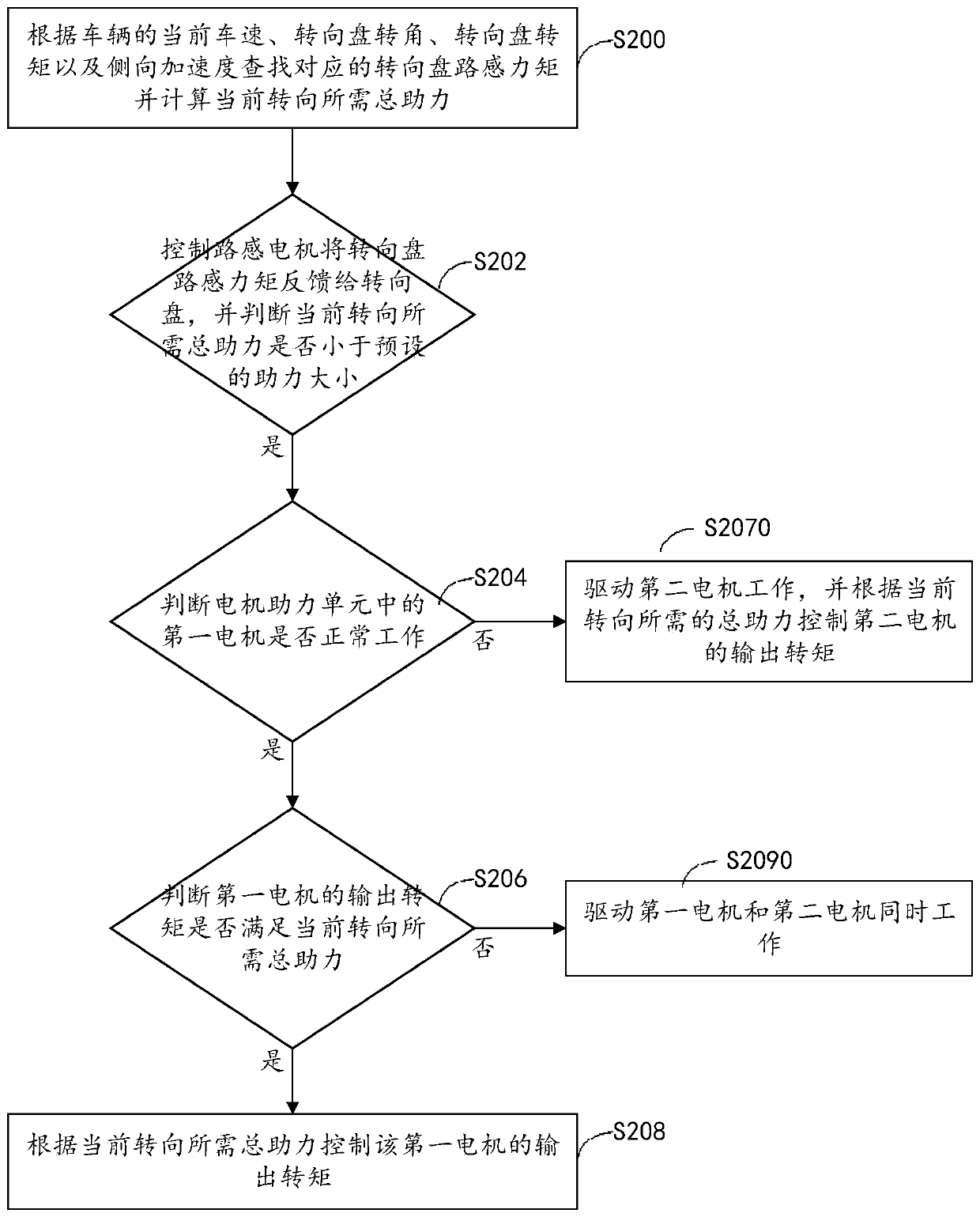
[0057] Such as image 3 As shown, the present application provides a steer-by-wire control method, which can be applied to the electronic control unit in the aforementioned first embodiment, and the method specifically includes the following steps:

[0058] Step S200: According to the vehicle's current vehicle speed, steering wheel angle, steering wheel torque and lateral acceleration, find the corresponding steering wheel torque and calculate the total power assistance required for the current steering.

[0059] Step S202: Control the road-sensing motor to feed back the road-sensing torque of the steering wheel to the steering wheel, and judge whether the total power required for the current steering is less than the preset power assist, if yes, go to step S204, if not, go to step S2050 .

[0060] Step S204: Determine whether the first motor in the motor assisting unit is working normally. The motor assisting unit includes the first motor and the second motor. If yes, go to ...

no. 3 example

[0086] Figure 6 A schematic structural block diagram of the steer-by-wire control device provided by the present application is shown. It should be understood that the device is different from the above-mentioned Figure 3 to Figure 6 Corresponding to the method embodiment in the second embodiment, the steps involved in the method in the second embodiment can be performed. The specific functions of the device can refer to the above description. To avoid repetition, the detailed description is appropriately omitted here. The device includes at least one software function module that can be stored in a memory in the form of software or firmware (firmware) or solidified in an operating system (operating system, OS) of the device. Specifically, the device includes: a calculation module 300 for finding the corresponding feedback torque according to the current vehicle speed, steering wheel angle, steering wheel torque and lateral acceleration of the vehicle and calculating the tot...


PUM


Abstract

The invention provides a steering-by-wire system and a control method thereof. The steering-by-wire system comprises a steering wheel, a first steering column, a first torque steering angle sensor, aroad sense feedback unit, an electronic control unit, a second steering column, a motor booster unit, a hydraulic booster unit and a circulating ball type hydraulic booster steering device, wherein the motor booster unit comprises a first motor steering booster unit and a second motor steering booster unit, the hydraulic booster unit comprises an electric hydraulic pump, an oil box, an electromagnetic directional valve and an oil pipe, the steering wheel is connected with the input end of the first steering column, the first torque steering angle sensor is arranged on the first steering columnin a sleeving manner, the road sense feedback unit is connected with the output end of the first steering column, the motor booster unit is connected with the input end of the second steering columnand is connected with the circulating ball type hydraulic booster steering device through the second steering column, the electric hydraulic pump, the oil box and the electromagnetic directional valveare connected in sequence, and the first torque steering angle sensor, the road sense feedback unit, the motor booster unit, the electric hydraulic pump and the electromagnetic directional valve areconnected with the electronic control unit.

Description

technical field [0001] The present application relates to the field of steer-by-wire, and in particular, to a steer-by-wire system and a control method thereof. Background technique [0002] Due to the limitation of installation space and cost, the power of the motor used in the steer-by-wire system is often small. Therefore, most of the existing steer-by-wire systems are designed for passenger cars with light weight front axles. For commercial vehicles with large front axle loads such as passenger cars and trucks, the steering torque that can be provided only by the motor is relatively limited, and the steering torque is mainly provided by hydraulic pressure, but the existing hydraulic system has large energy consumption and poor response. Disadvantages such as slow speed. Contents of the invention [0003] The purpose of the embodiments of the present application is to provide a steer-by-wire system and a control method thereof, which are used to solve the problems of h...

Claims


Application Information

Patent Timeline
Patent Type & Authority Applications(China)
IPC IPC(8): B62D5/04
CPCB62D5/0457
Inventor 薛仲瑾李亮王翔宇鲁之轩
Owner TSINGHUA UNIV
Why Eureka
Try Eureka