Thermoelectric conversion device based on liquid fuel combustion

A thermoelectric conversion device and technology of liquid fuel, applied in the directions of burners, combustion methods, combustion types, etc., can solve the problems of unfavorable outdoor movement of field workers, long charging time of rechargeable batteries, low energy density of batteries, etc., and achieve simple and fast Supplementary, light weight, increased contact area effect

Active Publication Date: 2019-12-20
XIAN UNIV OF SCI & TECH
View PDF8 Cites 2 Cited by
  • Summary
  • Abstract
  • Description
  • Claims
  • Application Information

AI Technical Summary

Problems solved by technology

However, rechargeable batteries and disposable batteries contain many hazardous substances that cause serious pollution to the environment. These hazardous substances pose potential dangers to human and animal health. Therefore, these batteries are mostly collected and processed separately, which requires Expensive price; the battery has a low energy density, and the quality of the battery is relatively large in practical applications, which is not conducive to the outdoor movement of field workers; in addition, the charging time for rechargeable batteries is relatively long

Method used


Image

  • Thermoelectric conversion device based on liquid fuel combustion
  • Thermoelectric conversion device based on liquid fuel combustion
  • Thermoelectric conversion device based on liquid fuel combustion

Examples


Embodiment Construction

[0022] The present invention will be described in detail below in conjunction with the accompanying drawings.

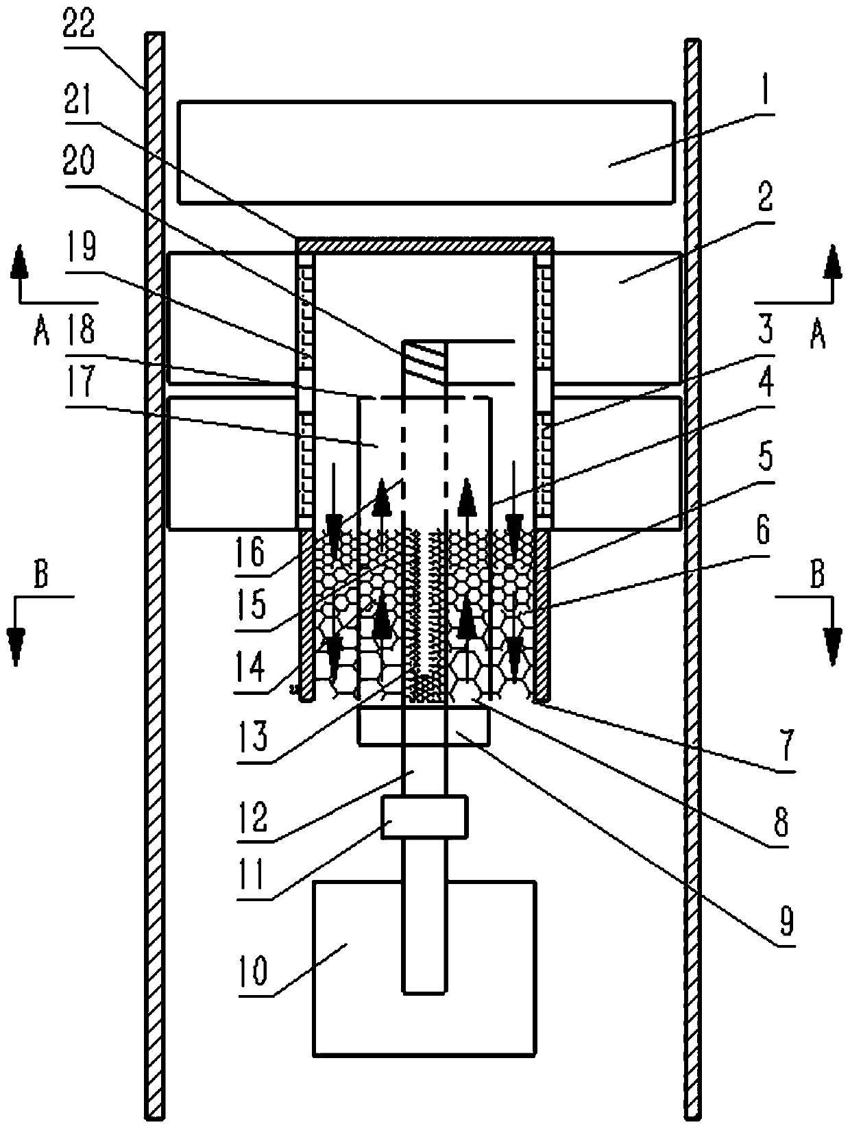
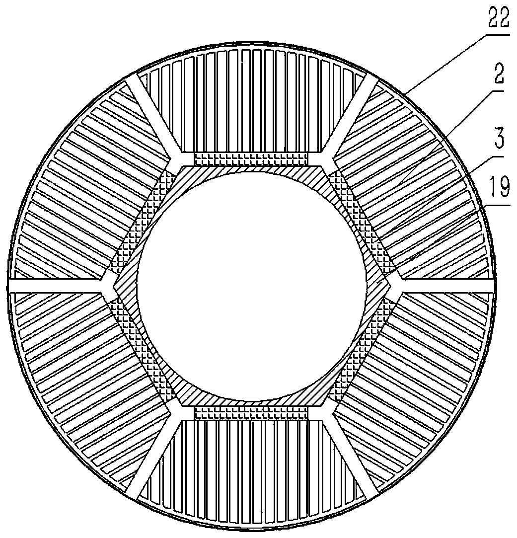
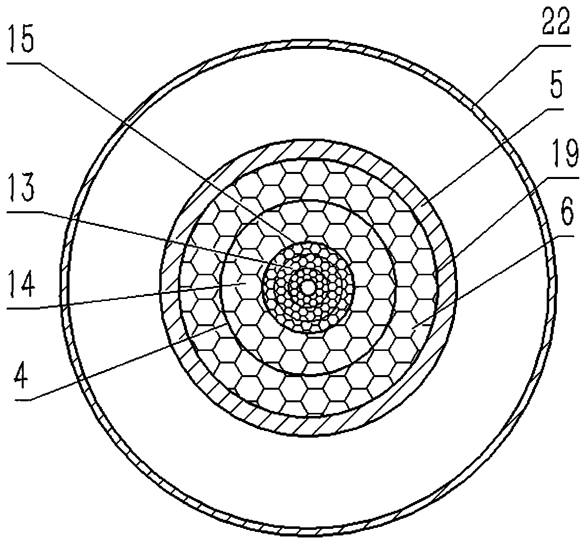
[0023] see figure 1 , figure 2 and image 3 , the present invention includes a combustion cylinder 19 arranged in the casing 22, a burner 4 is arranged inside the combustion cylinder 19, an ignition mechanism 20 is arranged on the top of the burner 4, a fuel evaporation tube 15 is arranged inside the burner 4, and the fuel evaporation tube 15 The inner lower part is filled with oil-absorbing porous medium 13, and the upper part is provided with a fuel vapor hole 16; the lower end of the fuel evaporation tube 15 is provided with an oil pump 11 and a fuel tank 10, and the fuel tank 10 is connected to the oil pump 11 through the oil tube 12, and the oil pump 11 is connected to the fuel evaporation tube 15 through the oil tube 12 The lower end is connected; a mixing chamber 17 is formed between the upper part of the fuel evaporation tube 15 and the inner wall of the b...


PUM


Abstract

The invention discloses a thermoelectric conversion device based on liquid fuel combustion. The thermoelectric conversion device based on liquid fuel combustion comprises a combustion cylinder. A combustor is arranged inside the combustion cylinder. An ignition mechanism is arranged on the top of the combustor. A fuel evaporation tube is arranged inside the combustor. The lower part of the interior of the fuel evaporation tube is filled with oil absorption porous media. Fuel vapor holes are formed in the upper part of the fuel evaporation tube. An oil pump is arranged at the lower end of the fuel evaporation tube, and is connected with the lower end of the fuel evaporation tube. A mixing chamber is formed between the upper part of the fuel evaporation tube and the inner wall of the combustor. An air delivery channel is formed between the lower part of the fuel evaporation tube and the inner wall of the combustor and communicates with the mixing chamber. A flue gas channel is formed between the outer wall of the combustor and the inner wall of the combustion cylinder. A thermoelectric power generation module is arranged on the outer wall of the combustion cylinder. According to thethermoelectric conversion device based on liquid fuel combustion, liquid fuel can be burned sufficiently, thermal energy is converted into electric energy, the environmental pollution caused by usingbatteries is reduced, the burden caused to a user during outdoor movement is reduced, and then it is avoided that electric equipment is cut off from a power source for a long time.

Description

technical field [0001] The present invention relates to the technical field of thermoelectric power generation, power supply technology, and burner technology, and in particular to a thermoelectric conversion device based on liquid fuel combustion. Background technique [0002] For military personnel, geological prospecting personnel and other workers who are often in the field, they need to use many electronic equipment, such as navigation equipment, communication equipment, camera equipment, etc. For these mobile equipment, the power supply is mainly provided by batteries. However, rechargeable batteries and disposable batteries contain many hazardous substances that cause serious pollution to the environment. These hazardous substances pose potential dangers to human and animal health. Therefore, these batteries are mostly collected and processed separately, which requires Expensive price; the battery has a low energy density, and the quality of the battery is relatively ...

Claims


Application Information

Patent Timeline
Patent Type & Authority Applications(China)
IPC IPC(8): F23D11/00F23D11/44F23J15/06F23L15/00H02N11/00
CPCF23D11/00F23D11/441F23J15/06F23L15/00H02N11/002Y02E20/34
Inventor 高怀斌宗守超苏航张传伟
Owner XIAN UNIV OF SCI & TECH
Why Eureka
Try Eureka