
Motor rotor, processing method thereof and synchronous reluctance motor

A technology for motor rotors and processing methods, which is applied in the manufacture of squirrel cage rotors, stator/rotor bodies, electrical components, etc., and can solve problems such as inability to improve motor performance, increase motor air gap, and reduce motor power factor

Pending Publication Date: 2019-12-20
GREE ELECTRIC APPLIANCES INC
View PDF0 Cites 3 Cited by
  • Summary
  • Abstract
  • Description
  • Claims
  • Application Information

AI Technical Summary

Problems solved by technology

[0004] However, the above-mentioned motor rotor only relies on the filling material for lamination connection to increase the outer diameter of the rotor, which increases the air gap of the motor, which will inevitably reduce the power factor of the motor, and cannot achieve the purpose of improving the performance of the motor.

Method used


Image

  • Motor rotor, processing method thereof and synchronous reluctance motor
  • Motor rotor, processing method thereof and synchronous reluctance motor
  • Motor rotor, processing method thereof and synchronous reluctance motor

Examples


Embodiment Construction

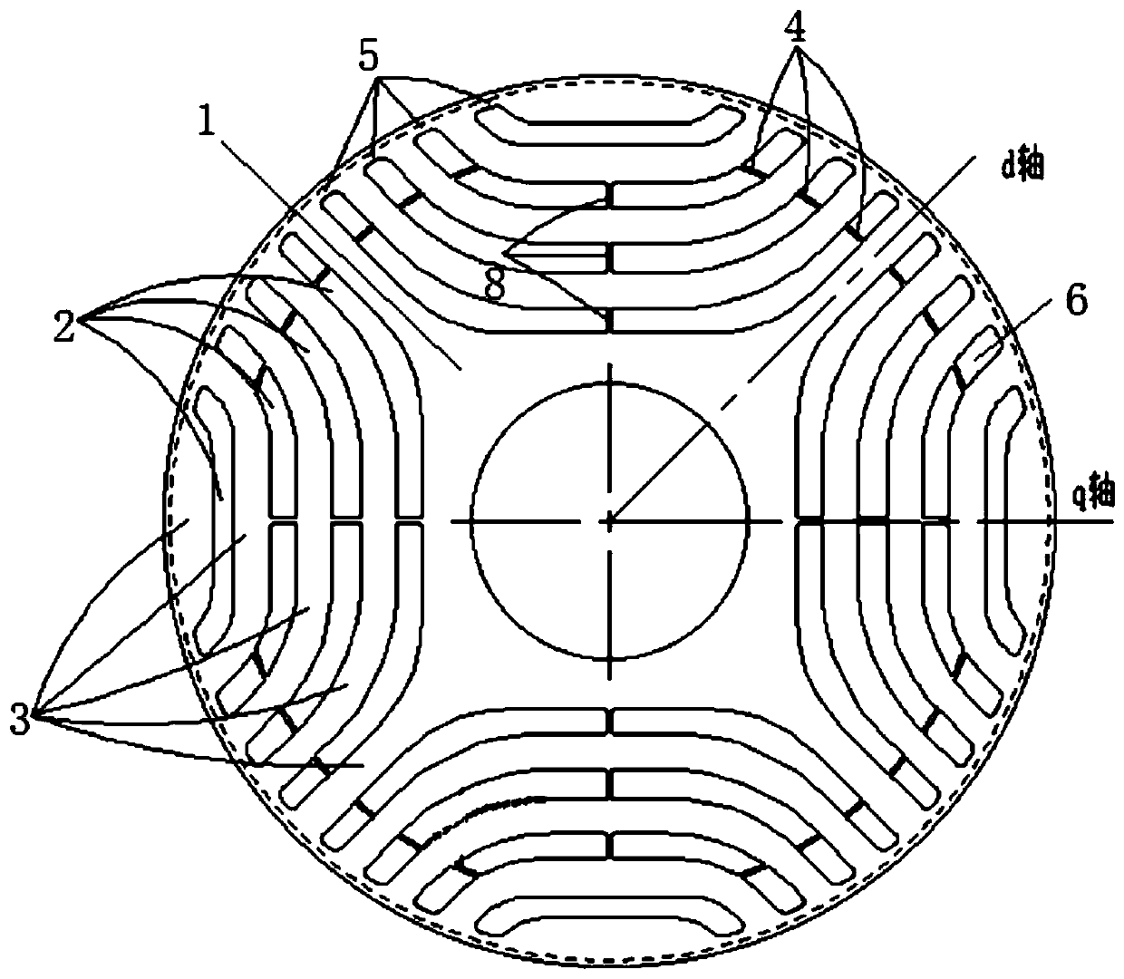
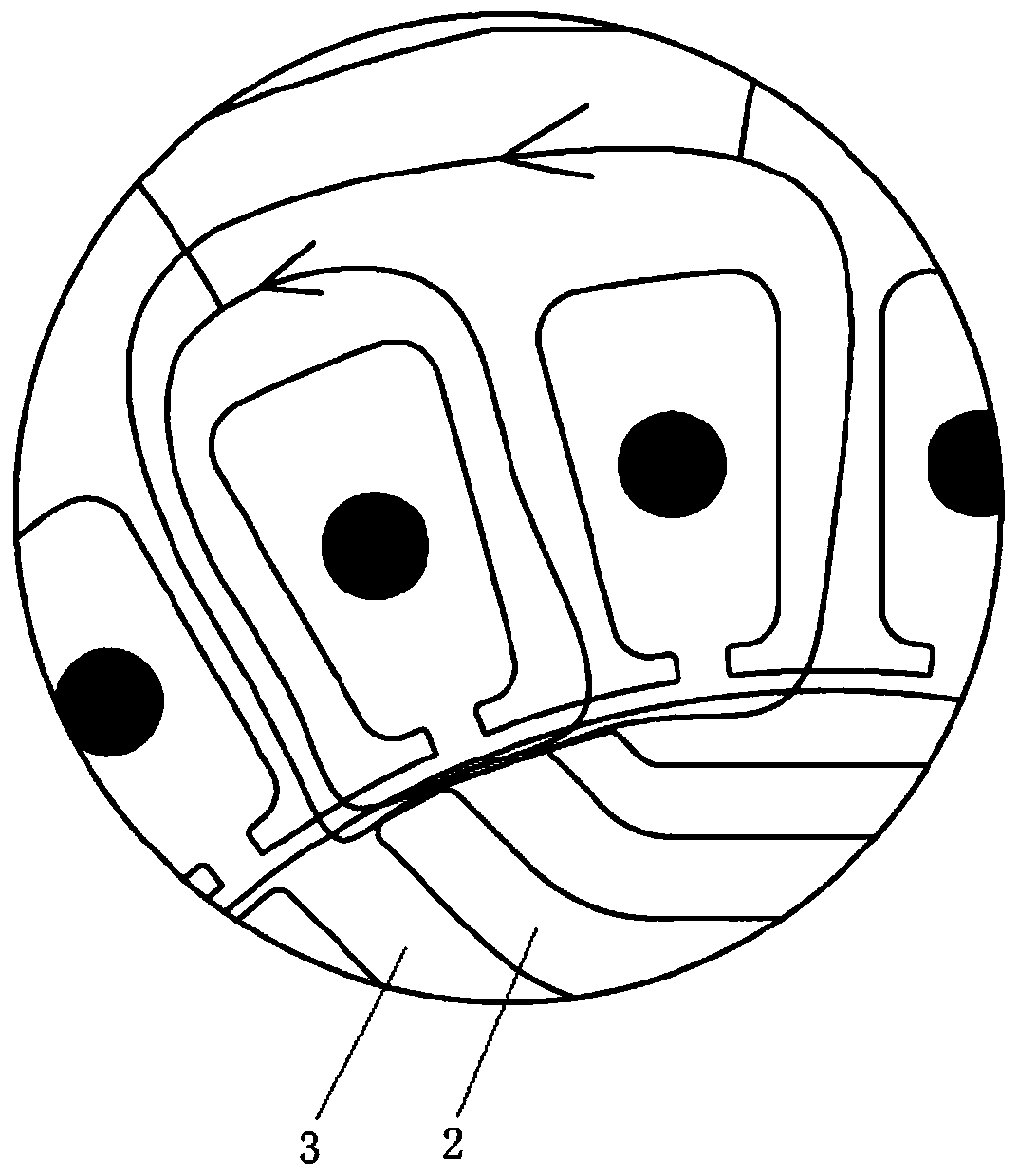
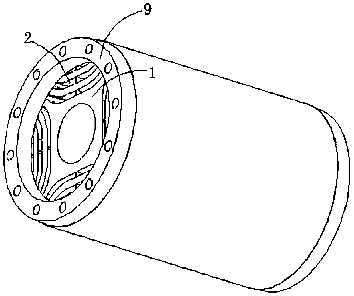
[0040] see in conjunction Figure 1 to Figure 5 As shown, according to the embodiment of the present application, the motor rotor includes a rotor core 1, and the rotor core 1 is provided with a plurality of magnetic barrier groups along the circumferential direction, and each magnetic barrier group includes a plurality of radially spaced magnetic fluxes. Barrier 2, magnetic conduction channels 3 are formed between adjacent magnetic flux barriers 2, each magnetic flux barrier 2 under the same pole is provided with a middle reinforcing rib 4, and the middle reinforcing rib 4 is arranged at both ends of the magnetic flux barrier 2, each magnetic flux barrier 2 The outer circumference of the rotor core 1 corresponding to the two ends of the barrier 2 is respectively provided with outer circular reinforcing ribs 5, the middle reinforcing rib 4 and the outer circular reinforcing rib 5 are arranged at intervals, the middle reinforcing rib 4, the outer circular reinforcing rib 5 and t...


PUM


Abstract

The invention provides a motor rotor, a processing method thereof and a synchronous reluctance motor. The motor rotor comprises a rotor core. The rotor core is provided with a plurality of magnetic barrier groups along a circumferential direction. Each magnetic barrier group comprises a plurality of magnetic flux barriers which are arranged at intervals along the radial direction; magnetic conduction channels are formed between the adjacent magnetic flux barriers; a middle reinforcing rib is arranged in each magnetic flux barrier under the same pole; the middle reinforcing ribs are arranged attwo ends of the magnetic flux barrier; outer circle reinforcing ribs are respectively arranged on the outer circumference of the rotor core corresponding to two ends of each magnetic flux barrier; the middle reinforcing rib and the outer circle reinforcing rib are arranged at intervals; a filling groove is formed among the middle reinforcing rib, the outer circle reinforcing rib and the magneticconduction channels on the two sides; the filling groove is filled with a filling layer; and the outer circumference of the rotor core is machined after the filling groove is filled with the filling layer, so that the radial width of the outer circle reinforcing rib can be adjusted. According to the motor rotor, the motor air gap can be reasonably adjusted, the motor power factor is improved, andthe motor performance is improved.

Description

technical field [0001] The present application relates to the technical field of motors, in particular to a motor rotor and a processing method thereof, and a synchronous reluctance motor. Background technique [0002] A synchronous reluctance motor is a motor that uses the reluctance torque generated by the difference between the direct-axis (d-axis) and the quadrature-axis (q-axis) reluctance of the motor to drive the rotor to drive the rotation of the shaft. path is closed. The excitation magnetic field of the synchronous reluctance motor is generated by the stator winding, so the power factor of the synchronous reluctance motor is lower than that of the permanent magnet motor of the same power, and the current is also larger than that of the permanent magnet motor. [0003] A method for manufacturing a reluctance motor rotor is proposed in the prior art. The rotor has a plurality of rotor laminations stacked one after the other in the axial direction, wherein each rotor...

Claims


Application Information

Patent Timeline
Patent Type & Authority Applications(China)
IPC IPC(8): H02K1/22H02K15/02
CPCH02K1/22H02K15/02H02K15/0012H02K2213/03
Inventor 胡余生李扬陈彬卢素华童童
Owner GREE ELECTRIC APPLIANCES INC
Learn More