Birotor permanent magnet synchronous reluctance motor and configuration method

A permanent magnet synchronous and reluctance motor technology, applied in synchronous motors with stationary armatures and rotating magnets, electromechanical devices, magnetic circuits, etc. , with high-order harmonics and other problems, to achieve the effect of improving torque density and material utilization, improving electromagnetic torque, and reducing dosage

Pending Publication Date: 2019-12-20
SHANDONG UNIV
View PDF0 Cites 4 Cited by
  • Summary
  • Abstract
  • Description
  • Claims
  • Application Information

AI Technical Summary

Problems solved by technology

However, these motors are not only complex in structure, but also have weak air gap flux density and high harmonics, resulting in low permanent magnet torque and high torque ripple
In addition, the inserted permanent magnets will worsen the stress condition of the ribs of the magnetic isolation bridge and limit the magnetic isolation bridge design with a relatively low significant ratio

Method used


Image

  • Birotor permanent magnet synchronous reluctance motor and configuration method
  • Birotor permanent magnet synchronous reluctance motor and configuration method
  • Birotor permanent magnet synchronous reluctance motor and configuration method

Examples


Embodiment 1

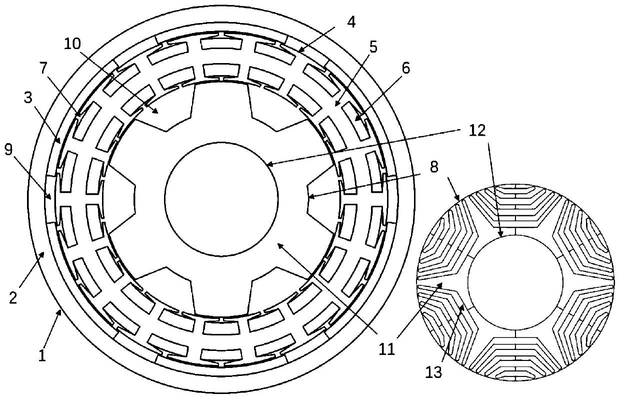
[0044] This embodiment discloses a dual-rotor permanent magnet synchronous reluctance motor, which is mainly composed of an outer rotor permanent magnet rotor 1 , an inner rotor reluctance rotor 8 and a stator 4 . Stator slots 7 are evenly opened inside and outside the stator 4 , and the stator 4 is located between the permanent magnet rotor 1 and the reluctance rotor 8 .

[0045]The stator 4 includes the stator core 5 and the stator winding 6. The inner and outer surfaces of the stator core 5 are slotted, and there are 36 stator slots 7 in total. to improve the working surface area and slot fill factor of the stator core.

[0046] The outer rotor permanent magnet rotor 1 includes a permanent magnet rotor core 2 and permanent magnets 3. The permanent magnets 3 have the same specifications and are evenly distributed along the circumferential direction. They are closely attached to the inner wall of the outer rotor core to form a surface-mounted permanent magnet rotor; Magnetic...


PUM


Abstract

The invention discloses a birotor permanent magnet synchronous reluctance motor and a configuration method. A rotating shaft, a reluctance rotor, a stator and a permanent magnet rotor are sequentiallyarranged from inside to outside, wherein stator grooves are uniformly formed inside and outside the stator, the stator is arranged between the permanent magnet rotor and the reluctance rotor, a d axis is defined as a center line of ferrite of the permanent magnet rotor, a q axis is defined as a center line of a salient pole of the reluctance rotor, a mounting angle of the two rotors on the rotating shaft is defined as an included angle between the d axis and the q axis, a superposition mechanism of torque components is changed by adjusting the mounting angle between the permanent magnet rotorand the reluctance rotor, so the permanent magnet torque and the reluctance torque reach the maximum values at the same current phase angle. The motor is advantaged in that on the premise of not increasing mechanical manufacturing and cooling difficulty of the motor, the electromagnetic torque, the power density and the efficiency are comprehensively improved, the torque pulsation and other electromagnetic properties are inhibited, and the rotor is flexible in structural design, simple in machining process and high in mechanical strength.

Description

technical field [0001] The invention belongs to the field of motor equipment, in particular to a dual-rotor permanent magnet synchronous reluctance motor and a configuration method. Background technique [0002] The statements in this section merely provide background information related to the present disclosure and do not necessarily constitute prior art. [0003] Permanent magnet motors are widely used in various fields due to their high torque density and high efficiency. However, the high price and limited supply of rare earth permanent magnet materials have brought great challenges to the development of permanent magnet motors. Therefore, it is imperative to study high-performance motors with fewer or zero rare-earth permanent magnets. [0004] The synchronous reluctance motor is considered as one of the alternatives due to the fact that it does not use permanent magnets, has a strong rotor structure and low cost, but it reduces the torque density, efficiency and pow...

Claims


Application Information

Patent Timeline
Patent Type & Authority Applications(China)
IPC IPC(8): H02K16/02H02K21/22H02K1/16H02K1/27H02K1/24
CPCH02K1/165H02K1/24H02K1/2786H02K16/02H02K21/22H02K2201/03
Inventor 赵文良张智源刘炎李玉靖
Owner SHANDONG UNIV
Why Eureka
Try Eureka