Revolving body surface high boss electrolytic machining tool electrode assembly and electrolytic machining method

A technology for processing tools and electrode components, which is applied in the direction of processing electrodes, electric processing equipment, electrochemical processing equipment, etc., can solve the problems of difficult control of processing stability, complex flow field, complex motion form, etc., and achieve favorable processing stability , avoid secondary corrosion, reduce the effect of stray corrosion

Active Publication Date: 2019-12-24
NANJING UNIV OF AERONAUTICS & ASTRONAUTICS
View PDF10 Cites 6 Cited by
  • Summary
  • Abstract
  • Description
  • Claims
  • Application Information

AI Technical Summary

Problems solved by technology

[0005] The flow field design in the above-mentioned patent is mainly proposed for the traditional copy-type electrolytic machining, but in the above-mentioned new thin-wall casing electrolytic machining method, the anode of the workpiece and the cathode of the tool are relatively rotating, and its movement form is more precise than that of traditional electrolytic machining. Complex, as the tool cathode feed depth continues to increase, the height of the boss on the anode surface of the workpiece is also increasing, the flow field at the top of the boss can always maintain a stable state, and the flow field in the machining gap on the side wall of the boss is more complicated , processing stability is difficult to control

Method used


Image

  • Revolving body surface high boss electrolytic machining tool electrode assembly and electrolytic machining method
  • Revolving body surface high boss electrolytic machining tool electrode assembly and electrolytic machining method
  • Revolving body surface high boss electrolytic machining tool electrode assembly and electrolytic machining method

Examples


Embodiment Construction

[0021] The implementation process of the present invention is illustrated in conjunction with the accompanying drawings:

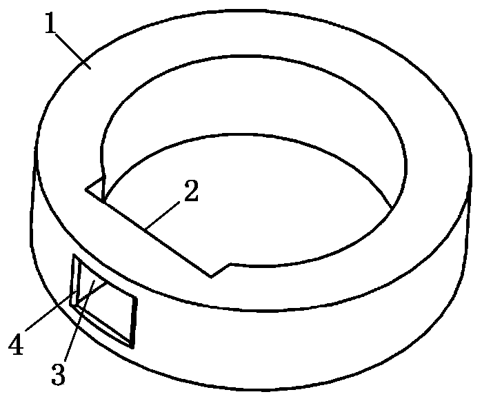
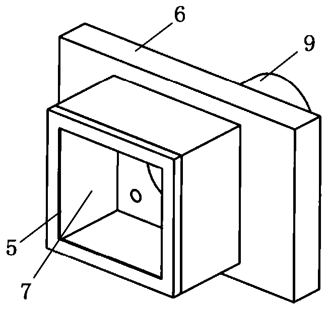
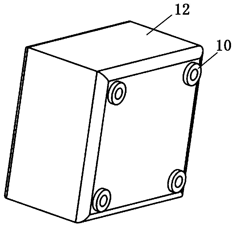
[0022] figure 1 It is a schematic diagram of the tool cathode structure; the tool cathode 1 is a rotator structure with a hollow groove structure 3 on its surface, a protruding circular structure 4 on the top of the groove structure 3, and a planar structure 2 inside the tool cathode 1. figure 2 It is a schematic diagram of the structure of the first insulating cavity; the first insulating cavity 8 is installed on the plane structure 2 inside the tool cathode 1, and the outer side of the first insulating cavity cavity 7 is connected with the inner wall and groove structure of the protruding round structure 4 on the tool cathode 1 3 side walls fit tightly. image 3 It is a schematic diagram of the structure of the second insulating cavity; there are four bottom mounts 10 at the bottom of the second insulating cavity 12, which are fixed inside the first in...


PUM


Abstract

The invention provides a revolving body surface high boss electrolytic machining tool electrode assembly and an electrolytic machining method, and belongs to the technical field of electrolytic machining. The method is characterized in that the tool electrode assembly comprises a tool cathode, a first insulating cavity and a second insulating cavity; and the tool cathode is of a revolving body structure, the surface of the tool cathode is provided with a hollowed-out groove structure, and an opening of the groove structure is of a protruding guide circle structure; the outer side of the firstinsulating cavity is fixedly attached to the inner wall of the protruding guide circular structure, the side wall of the groove structure and the inner side plane of the tool cathode, and the other end of the first insulating cavity is of a tubular structure; the outer side corner of the second insulating cavity is in an arc transition, and the second insulating cavity is fixed in the first insulating cavity through a bottom mounting seat and forms an electrolyte flow channel with the first insulating cavity. According to the method, the electrolyte flowing from the side surface through a first electrolyte inlet can provide a stable flow field for the processing region at the revolving surface, and the electrolyte flowing from the inner side of the groove structure through a second electrolyte inlet can ensure the uniformity of the flow field of the machining region at the side wall of the boss, so that the electrolytic machining stability of the high boss on the surface of the revolving body is ensured.

Description

technical field [0001] The invention adopts an electrode assembly and an electrolytic machining method of an electrolytic machining tool with a high convex platform on the surface of a rotating body, and belongs to the technical field of electrolytic machining. Background technique [0002] Electrolytic machining is the rapid removal of workpiece material using electrochemical reactions. Compared with traditional machining methods, electrolytic machining is non-contact machining, and has the advantages of no tool loss, no residual stress, no cold hardening, no plastic deformation, and low surface roughness during the machining process. Therefore, electrolytic machining is suitable for processing thin-walled parts, space-complex curved surfaces, and difficult-to-cut superalloy materials. [0003] As an important part of an aero-engine, the casing is a large thin-walled part with a complex concave-convex surface. Its material is mostly high-temperature alloy or titanium alloy...

Claims


Application Information

Patent Timeline
Patent Type & Authority Applications(China)
IPC IPC(8): B23H3/04B23H3/10B23H3/00
CPCB23H3/00B23H3/04B23H3/10
Inventor 王登勇何斌张军曹文见李金正任智源朱增伟
Owner NANJING UNIV OF AERONAUTICS & ASTRONAUTICS
Why Eureka
Try Eureka