
an optical component 2 Laser remelting and gasification composite polishing method

An optical element, laser remelting technology, applied in laser welding equipment, metal processing equipment, welding equipment and other directions, can solve the problems of difficult to determine the laser incident angle, difficult to remove ablation vapors, low melting and polishing efficiency, etc., to avoid The effect of secondary pollution, convenient operation and simple operation

Active Publication Date: 2021-04-23
NANJING UNIV OF SCI & TECH
View PDF14 Cites 0 Cited by
  • Summary
  • Abstract
  • Description
  • Claims
  • Application Information

AI Technical Summary

Problems solved by technology

The main disadvantages of fusion polishing are relatively low efficiency, residual thermal stress, and easy porosity; gasification polishing has problems such as the higher the polishing accuracy, the more difficult it is to determine the laser incident angle, the difficulty in removing ablation gasification, and the poor polishing effect.

Method used


Image

  • an optical component  <sub>2</sub> Laser remelting and gasification composite polishing method
  • an optical component  <sub>2</sub> Laser remelting and gasification composite polishing method
  • an optical component  <sub>2</sub> Laser remelting and gasification composite polishing method

Examples


Embodiment 1

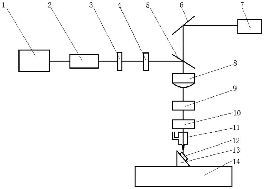
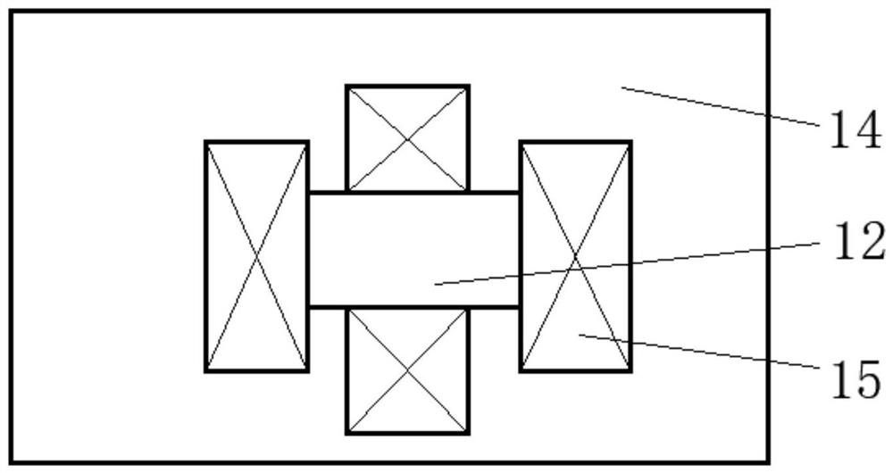
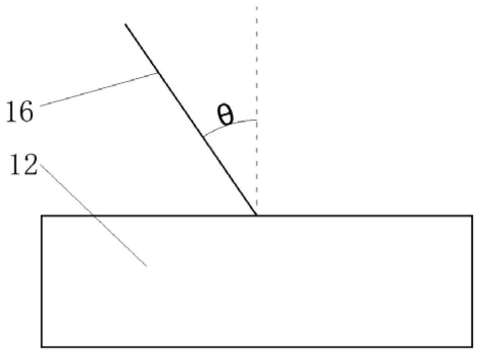
[0037]CO for optical components2Laser remelting and gasification composite polishing, the matrix material is a melted stone. The experiment is installed with CO2Tensile cleansing between laser polishing devices. First, the surface of the optical element is cleaned by the ultrasonic cleaner, and then dry the optical element with a hairdryer in the normal temperature mode, and the sample 12 is placed infigure 1 The displayed electric shifting table 14, and adoptedfigure 2 The method shown is fixed, turned on the laser 1, adjusts the laser parameters: the laser power is 40W, the frequency is 10 kHz, the duty ratio is 4mm, the spot is 10mm, the deguscad is 0.08 mm, the scan speed is 40mm. / S, drawimage 3 The parallel trajectory shown, introduces a laser system, and determines the set laser parameters, and positions the workpiece to the initial machining position and the optical element is remelted and polished by the CCD observation system. After the polishing is completed, the sample ...


PUM


Abstract

The invention relates to an optical component CO 2 Laser remelting and gasification composite polishing method, the method uses CO 2 Laser parallel scanning method, by changing the laser power, repetition frequency, and spot diameter, remelt polishing and gasification polishing are alternately layered and scanned on optical components. . The invention is suitable for high-efficiency and high-precision polishing of various optical elements.

Description

Technical field[0001]The present invention relates to the polishing of the optical element, specifically a optical element CO2Laser Relieving and Hydrating Composite Polishing Method.Background technique[0002]The polishing method of the optical element is divided into contact polishing and non-contact polishing according to whether or not directly exposed to the processing parts. It mainly has airbag polishing, gadget polishing, ion bundle polishing, laser polishing, etc., the former belongs to the contact polishing Easy to make impurities Embed an optical element, the latter belongs to non-contact polishing, which does not introduce impurities into optical components, no pressure stresses, and low residual stress. Laser polishing is unlike magnetoromed polishing on the environment, target, etc., has a wide range of applications, convenient operation, high precision, and high efficiency.[0003]According to the method of laser and material, laser polishing can be divided into hot poli...

Claims


Application Information

Patent Timeline
Patent Type & Authority Patents(China)
IPC IPC(8): B23K26/352B23K26/354B23K26/00
CPCB23K26/00B23K26/352B23K26/354
Inventor 李晓鹏陆广华支新涛王大森王克鸿袁松梅周琦彭勇
Owner NANJING UNIV OF SCI & TECH
Learn More