Split type thermostatic valve

A thermostatic valve and split-type technology, applied in the field of thermostatic sanitary ware, can solve the problems that the thermostatic valve structure is difficult to meet the needs of manufacturing, affect product forming and subsequent processing, reduce the stability of the valve body forming process, etc. Production difficulty, simple and convenient installation process, stable and reliable structure

Pending Publication Date: 2019-12-27
潍坊百乐卫浴制品有限公司
View PDF1 Cites 2 Cited by
  • Summary
  • Abstract
  • Description
  • Claims
  • Application Information

AI Technical Summary

Problems solved by technology

For example, the Chinese patent with the application number CN201420741028.6 provides a new type of thermostatic faucet, in which a hot water inlet channel, a hot water outlet channel, a mixed water inlet channel and a mixed water outlet channel are opened in the valve body, see its manual and attached drawings It can be seen that the valve body is an integrated configuration, the water channels in the valve body are staggered, the structure is complex and there are many partition walls
In the prior art, when manufacturing this type of valve body, injection molding is often used for integral molding, which often has higher requirements for production technology and manufacturing precision.
However, due to the limitation of the valve body structure, more mandrels will be used, and the longer the water channel, the longer the mandrel required, which reduces the stability of the valve body forming process, and ultimately affects the molding and follow-up of the product. Processing, in actual production, generally has problems such as low production efficiency, low yield rate, and high scrap rate, resulting in waste of resources
Therefore, the existing thermostatic valve structure is difficult to meet the needs of manufacturing

Method used


Image

  • Split type thermostatic valve
  • Split type thermostatic valve
  • Split type thermostatic valve

Examples


Embodiment 1

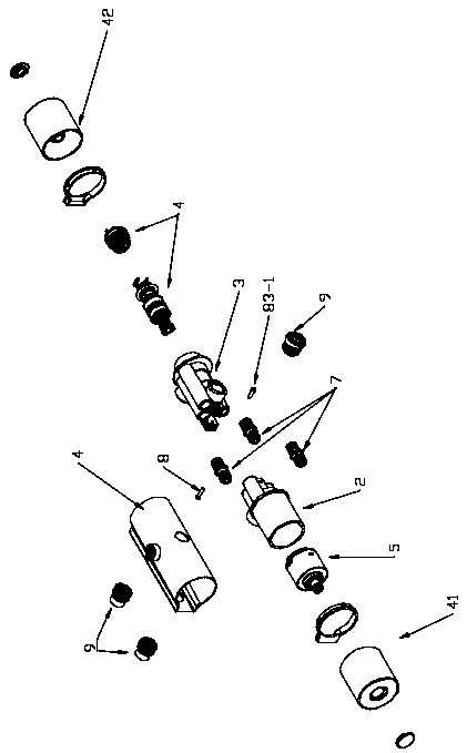
[0048] Such as Figure 1-6 As shown, a split-type thermostatic valve includes a main valve body 1, a casing 4, a switch spool 5, and a thermostatic spool 6. The casing 4 is a hollow cylindrical structure in the middle, and also includes a switch spool handwheel 41, a thermostatic The spool hand wheel 42 is connected with the handles of the switch spool 5 and the thermostatic spool 6 respectively, and the rotating hand wheel drives the handle to rotate. The shell 4 is also provided with an opening for the pipe joint 9 to pass through.

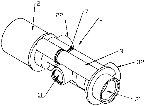
[0049] Such as Figure 1-5 As shown, the main valve body 1 is a split structure, including the left valve body 2, the right valve body 3 and the plug-in parts 7 for connecting the left and right valve bodies. The main valve body 1 is also provided with at least one set for connecting Fasten the fastening parts 8 of the left valve body 2 and the right valve body 3.

[0050] This embodiment adopts a split structure, shortens the process length ...

Embodiment 2

[0071] Compared with the first embodiment, this implementation mainly provides another fastening method for the left and right valve bodies.

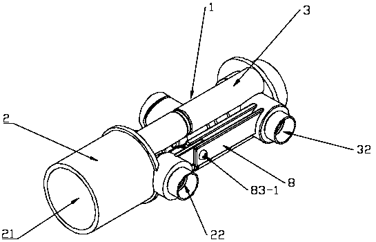
[0072] Such as Figure 7-15 As shown, the main valve body 1 is a split structure, including the left valve body 2, the right valve body 3 and the plug-in parts 7 for connecting the left and right valve bodies. The main valve body 1 is also provided with at least one set for connecting Fasten the fastening parts 8 of the left valve body 2 and the right valve body 3. In this embodiment, the plug-in part 7 is integrally formed with the water flow channel 12 of the right valve body 3, the water flow channel of the left valve body 2 is open and provided with a socket 13, and the plug-in part 7 of the right valve body 3 is inserted into the left valve In the socket 13 of the body 2, the assembly of the left and right valve bodies is realized. In this embodiment, a set of fastening parts 8 is provided on each docked water flow channel. In th...

Embodiment 3

[0093] Compared with Example 2, such as Figure 16 As shown, the difference in this embodiment is that the thermal sensor 64 is a memory alloy spring 64B. Memory alloy springs are gradually being applied because of their excellent thermal sensitivity. combine Figure 10 , 12 , 13, the current limiting assembly 66 in this embodiment is a single sliding sleeve 66B, and the two ends of the single sliding sleeve 66B respectively form a water inlet gap for heating and cold water circulation with the limiting step 35 of the current limiting assembly and the end of the valve head 63 , the middle part of the single sliding sleeve 66B is provided with a water-passing ring step, the return spring 65 and the memory alloy spring 64B are arranged on the left and right sides of it, and pushing the single sliding sleeve 66B affects its side end and the limiting step 35 of the current limiting component, the valve The size of the gap at the end of the head 63 then affects the actual water ...


PUM


Abstract

The invention belongs to the field of thermostatic bathrooms, and relates to a thermostatic valve, in particular to a split type thermostatic valve. The split type thermostatic valve comprises a mainvalve body, a shell, a switch valve element and a thermostatic valve element, the main valve body is composed of a left valve body and a right valve body, the switch valve element is arranged in the left valve body, the thermostatic valve element is arranged in the right valve body, a plurality of water flow channels are correspondingly formed in the left valve body and the right valve body, the water flow channels in the left valve body and the corresponding water flow channels in the right valve body are assembled in a butt joint mode and communicate with each other through plug-in components, and at least one group of fastening components used for connecting and fastening the left valve body and the right valve body are further arranged on the main valve body. According to the split type thermostatic valve, two modes of connecting and locking the left valve body and the right valve body are provided, in the first mode, the fastening components are arranged at the positions, outsidethe water flow channels, of the valve bodies, in the second mode, the fastening components are directly arranged on the water flow channels, whether the plug-in structures are double-plug or single-plug structures, the two modes are applicable, and the two locking modes are ingenious in design and can be widely applied to valve bodies of various thermostatic valves.

Description

technical field [0001] The invention belongs to the field of constant temperature sanitary ware, and relates to a constant temperature valve, in particular to a split type constant temperature valve. Background technique [0002] A thermostatic valve is a plumbing device that mixes cold water and hot water and outputs warm water. Its core temperature control mechanism is a thermostatic valve core, which is basically composed of a main body, a temperature sensing element, a return spring, a piston, etc., and automatically adjusts the mixing ratio of cold and hot water through the difference between the outlet temperature of the mixed water and the set temperature, so that the outlet water temperature in a basically constant state. [0003] A common thermostatic valve, also known as a thermostatic faucet, generally includes a casing, a main valve body, a switch spool for controlling water volume and switching, and a thermostatic spool. There are multiple independent water flo...

Claims


Application Information

Patent Timeline
Patent Type & Authority Applications(China)
IPC IPC(8): F16K11/07F16K31/70
CPCF16K11/0655F16K11/07F16K31/002
Inventor 薛令斌
Owner 潍坊百乐卫浴制品有限公司
Why Eureka
Try Eureka