Resonant cavity-based lateral current limiting high-efficiency light-emitting diode

A light-emitting diode and lateral current technology, applied in circuits, electrical components, semiconductor devices, etc., can solve problems such as Joule heat, reduced light extraction rate, and low external quantum efficiency

Active Publication Date: 2019-12-27
BEIJING UNIV OF TECH
View PDF13 Cites 3 Cited by
  • Summary
  • Abstract
  • Description
  • Claims
  • Application Information

AI Technical Summary

Problems solved by technology

The reasons for its low external quantum efficiency are as follows: firstly, when the current passes through the upper electrode (100), the current is mainly concentrated in a part of the area below the electrode, and because the reflectivity of the upper Bragg reflector (200) is low, the total The thickness is small, and the current injected from the upper electrode reaches the active area and under

Method used


Image

  • Resonant cavity-based lateral current limiting high-efficiency light-emitting diode
  • Resonant cavity-based lateral current limiting high-efficiency light-emitting diode
  • Resonant cavity-based lateral current limiting high-efficiency light-emitting diode

Examples


Embodiment Construction

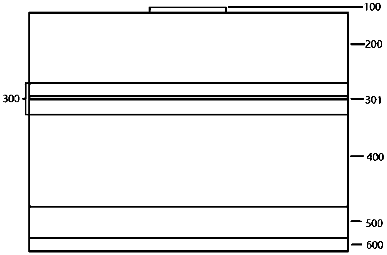
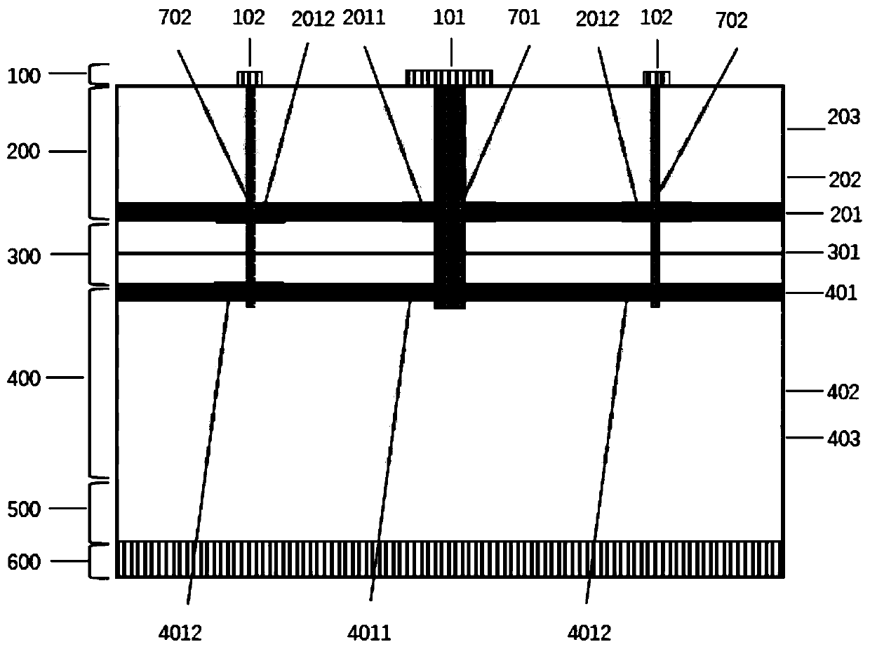
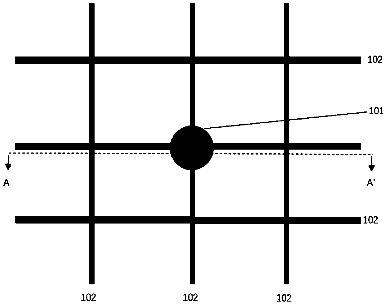
[0016] 1. A resonant cavity-based lateral current confinement high-efficiency light-emitting diode, comprising an upper electrode (100), an upper Bragg reflector (200), a resonant cavity (300), a lower Bragg reflector (400), and a substrate from top to bottom Bottom (500), lower electrode (600). The upper electrode (100) is composed of a pressure welding upper electrode (101) and a current expansion upper electrode (102); the upper Bragg reflector (Distributed Bragg Reflector Mirror, DBR) (200) is composed of a low refractive index material layer (202) and a high The refractive index material layers (203) are alternately formed, the active region (301) is located in the middle of the resonant cavity (300), and the lower Bragg reflector (400) is composed of low refractive index material layers (402) and high refractive index material layers (403) alternately constitute. The bottom layer of material layer of the upper Bragg reflector (200) is an upper DBR easily oxidizable mate...


PUM


Abstract

The invention discloses a resonant cavity-based lateral current limiting high-efficiency light-emitting diode and belongs to the field of semiconductor electronics. The resonant cavity-based lateral current limiting high-efficiency light-emitting diode comprises an upper electrode, an upper Bragg reflector, a resonant cavity, a lower Bragg reflector, a substrate and a lower electrode which are distributed sequentially from top to bottom; the upper electrode consists of an upper pressure welding electrode and an upper current expanding electrode; low-refractive-index material layers and high-refractive-index material layers which are arranged alternately are adopted to form the upper Bragg reflector and the lower Bragg reflector separately; an upper DBR oxidizable material layer is arrangedat the bottom of each of the upper Bragg reflector and the lower Bragg reflector; an active region is located in the middle of the resonant cavity; and a lower DBR oxidizable material layer is arranged at the top of the active region. The diode further comprises an upper expansion electrode lateral oxide layer, a lower expansion electrode lateral oxide layer, an upper pressure welding electrode lateral oxide layer, a lower pressure welding electrode lateral oxide layer, an expansion electrode lateral oxide layer, an extension electrode dielectric layer and a pressure welding electrode dielectric layer. According to the diode of the invention, the lateral oxide layers are used for limiting the transverse flow of current, so that carriers are prevented from being injected into the active region under the top electrode; the resonant cavity structure in a vertical direction is used in combination; and therefore, the light emitting diode has the advantages of high efficiency, good thermalperformance and stable radiation wavelength.

Description

technical field [0001] The invention relates to a resonant cavity light emitting diode (Resonant Cavity Light Emitting Diode, RCLED), in particular to a resonant cavity-based lateral current-limited high-efficiency light-emitting diode, which belongs to the technical field of semiconductor electronics. Background technique [0002] At present, as a new type of light source, light-emitting diodes have a huge market in the fields of automobile taillights, lighting displays, and optical fiber communications. The luminous intensity of LED is determined by luminous efficiency, and luminous efficiency is determined by internal quantum efficiency and external quantum extraction efficiency. Among them, the internal quantum efficiency can be increased to 90% or even close to 100% due to the progress of various epitaxy technologies and control technologies, while the external quantum extraction efficiency is still low due to the influence of electrode absorption and internal total ref...

Claims


Application Information

Patent Timeline
IPC IPC(8): H01L33/10H01L33/14H01L33/38H01L33/00
CPCH01L33/0062H01L33/10H01L33/145H01L33/382
Inventor 李建军王军
Owner BEIJING UNIV OF TECH
Why Eureka
Try Eureka