
Flexible flare line system based on expansion joint compensation

A flexible system and torch pipeline technology, applied in expansion compensation devices, pipe components, pipes/pipe joints/pipe fittings for pipelines, etc., can solve the problems of low pipeline flexibility and reliability, high pipeline stress, and waste of raw materials, etc. Achieve the effect of improving pipeline safety and reliability, reducing pipeline stress and pipeline support load, and reducing pipeline diameter

Pending Publication Date: 2019-12-31
LUOYANG SUNRUI SPECIAL EQUIP
View PDF0 Cites 0 Cited by
  • Summary
  • Abstract
  • Description
  • Claims
  • Application Information

AI Technical Summary

Problems solved by technology

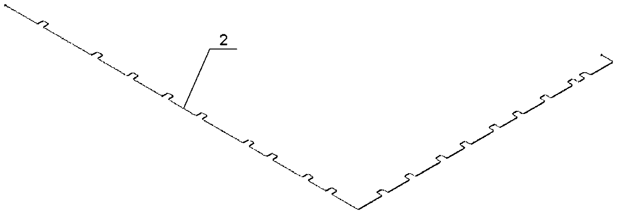
With the implementation of multiple national "refining and chemical integration" base plans, petrochemical and post-derivative production facilities such as petrochemical and coal chemical industries are more characterized by expanded production scale, joint construction and joint production, and centralized supply of public works. The diameter of the torch pipeline It is getting bigger and bigger, and the maximum diameter reaches φ3m. Due to the large diameter of the pipeline, the lateral extension of the Π-shaped bend compensation usually reaches about 100-120 meters, which not only consumes a lot of raw materials economically, but also It occupies a large amount of land, and at the same time, it needs to use a large number of steel structure supports to restrain the shrinkage and deformation of the pipeline, and the investment cost is high; in terms of safety and stability, such as figure 1 As shown, if the Π-shaped bend compensation is used, the pressure drop of the pipeline is large, there are many parts with high stress in the pipeline, the force on the bracket is large, and the flexibility and reliability of the pipeline are low.

Method used


Image

  • Flexible flare line system based on expansion joint compensation
  • Flexible flare line system based on expansion joint compensation
  • Flexible flare line system based on expansion joint compensation

Examples


Embodiment Construction

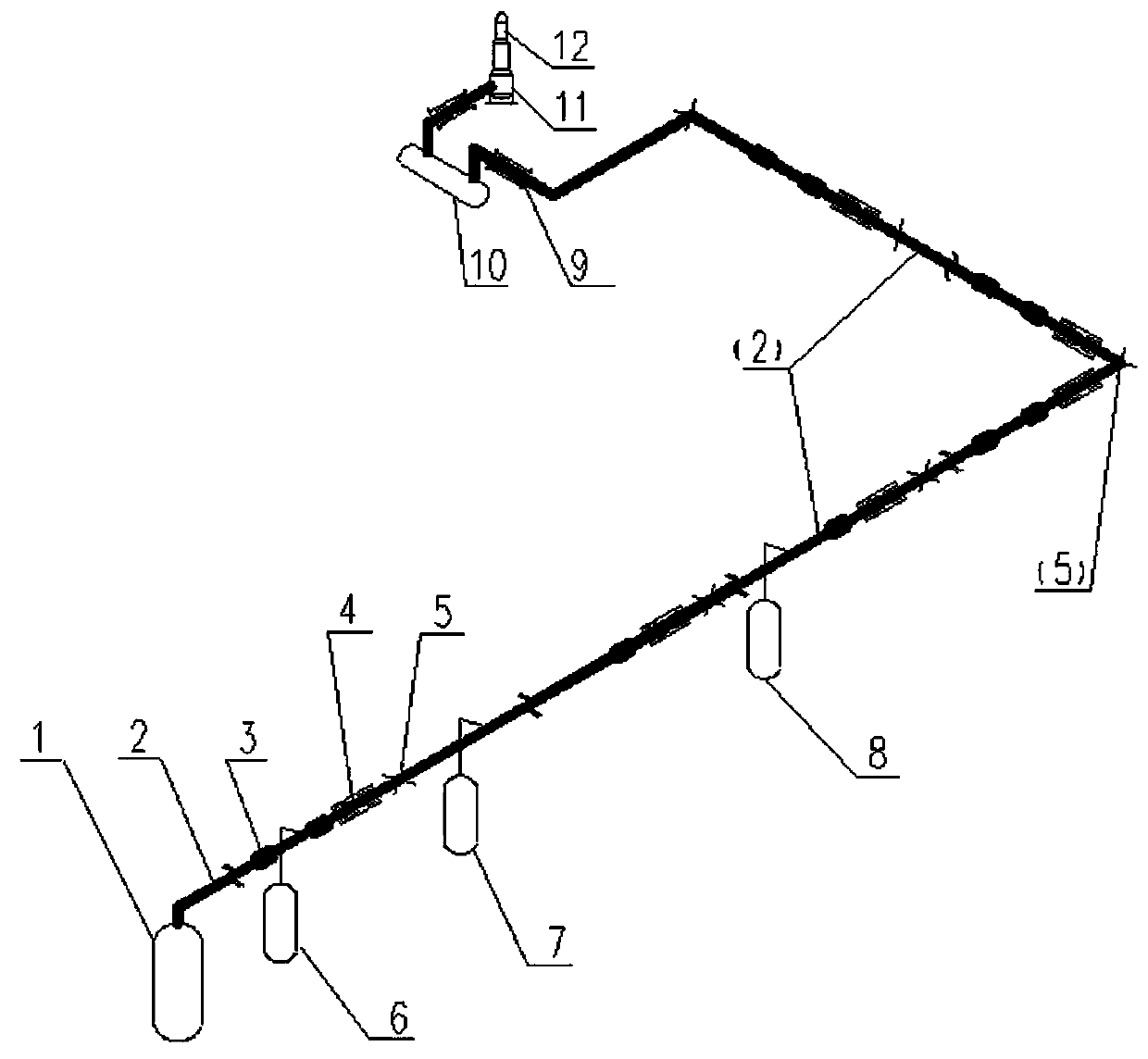
[0024] Such as figure 2 As shown, a flare pipeline flexible system based on expansion joint compensation includes an overhead torch main pipe 2, a reaction device and a liquid separation tank 10, the reaction device and liquid separation tank 10 are connected to the flare main pipe 2, and the reaction device can be There are multiple sets. The medium discharged from the reaction device enters the torch main pipe 2, and enters the liquid separation tank 10 through the torch main pipe 2. The torch main pipe 2 is composed of a straight pipe section 21 and a curved pipe section 22. The system also includes an explosion-proof straight-through external pressure straight pipe pressure balance The expansion joint 4 and the compound expansion joint 9 of the universal hinge pull rod, the thermal displacement of the straight pipe section 21 is compensated by the explosion-proof straight-through external pressure straight pipe pressure balance expansion joint 4, and the thermal displaceme...


PUM


Abstract

The invention relates to a flexible flare line system based on expansion joint compensation. The system comprises a flare main pipe, a reaction device and a delivery flask by overhead laying. The reaction device and the delivery flask are connected to the flare main pipe, and the flare main pipe is composed of a straight pipe section and a turned pipe section. The system also comprises an anti-explosion straight-through type external pressure straight pipe pressure balance expansion joint and a universal hinge pull rod compound expansion joint. The anti-explosion straight-through type externalpressure straight pipe pressure balance expansion joint is used for flexible compensation of the straight pipe section and the universal hinge pull rod compound expansion joint is used for flexible compensation of the turned pipe section. The system solves an arrangement design problem of a flare line of a large energy source chemical device, improves the safe reliability of the flare line and lowers the investment, and the economical efficiency of the flare line system is improved by over 30%.

Description

technical field [0001] The invention relates to a flexible compensation technology for a flare pipeline of an energy chemical device, in particular to a flexible flare pipeline system based on expansion joint compensation. Background technique [0002] The composition of the flare system usually consists of four parts: the flare gas separator tank, the flare gas water seal tank, the flare, and the flare pipeline. The main function of the flare system is to collect the flammable and toxic gases emitted by the energy and chemical production equipment under normal production, start / stop and accident conditions through the flare facilities and burn them safely to ensure the safety of the equipment and reduce gas emissions pollution of the atmospheric environment. The pipeline network of the flare system is the basis for the safe operation of the discharge device, that is, the flare pipeline is the last line of defense for energy and chemical equipment, and its safety and reliab...

Claims


Application Information

Patent Timeline
Patent Type & Authority Applications(China)
IPC IPC(8): F16L51/02F16L51/03
CPCF16L51/02F16L51/03
Inventor 张爱琴李德雨陈继志李张治侯伟
Owner LUOYANG SUNRUI SPECIAL EQUIP
Learn More