
Wafer lithography device

A lithography equipment and wafer technology, applied in the processing of photosensitive materials, etc., can solve problems such as double-ring defects, backsplash, etc., and achieve the effects of reducing impurities, not easy to remain, and increasing the flow rate

Inactive Publication Date: 2019-12-31
泉州洛江泰润机械科技有限公司
View PDF0 Cites 2 Cited by
  • Summary
  • Abstract
  • Description
  • Claims
  • Application Information

AI Technical Summary

Problems solved by technology

[0002] Integrated circuit technology is the basic technology required by all electronic products today. The carrier of integrated circuit technology is the integrated circuit board. The most important part of the integrated circuit board is the wafer. The lithography process of wafer manufacturing is the most critical. If Photolithography fails, the wafer is discarded and can no longer be used. Under the action of light, the pattern on the mask plate is transferred to the wafer substrate with the help of photoresist, and the wafer needs to be developed in the developing tank. At this time , when the sprayed deionized water will flow away along the drain pipe, when the wafer is rotated, the impurities containing ionized water reactants on the spray head controlled by the manipulator will cause backsplash when the impurities containing ionized water reactants are thrown onto the CUP, and some reactants will be splashed shot into the wafer being processed, resulting in a double-ring defect

Method used


Image

  • Wafer lithography device
  • Wafer lithography device
  • Wafer lithography device

Examples


Embodiment

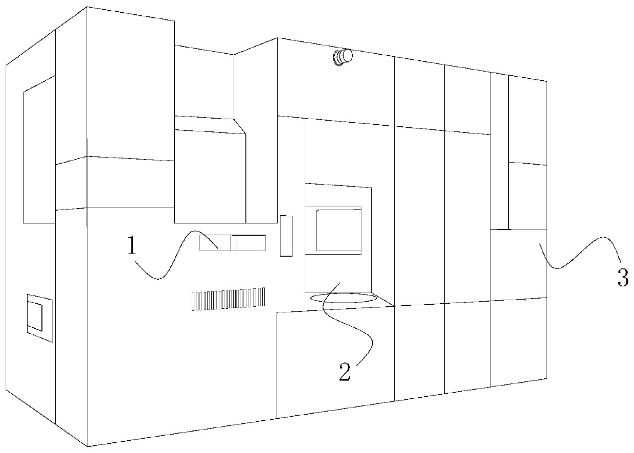
[0026] see Figure 1-Figure 5 , the present invention provides a wafer lithography equipment, the structure of which includes a window 1, an operating table 2, a main body 3, a nozzle structure, a developing tank, an automatic alignment system, a frame damping system, etc., and the main body 3 is provided with a Operating table 2, a window 1 is installed on one side of the operating table 2, a nozzle is installed inside the main body 3, a developing tank is provided at the bottom of the nozzle structure, and an automatic alignment system is provided on the horizontal side of the developing tank , A frame damping system is installed directly under the automatic alignment system, and the frame damping system is movably matched with the developing tank.

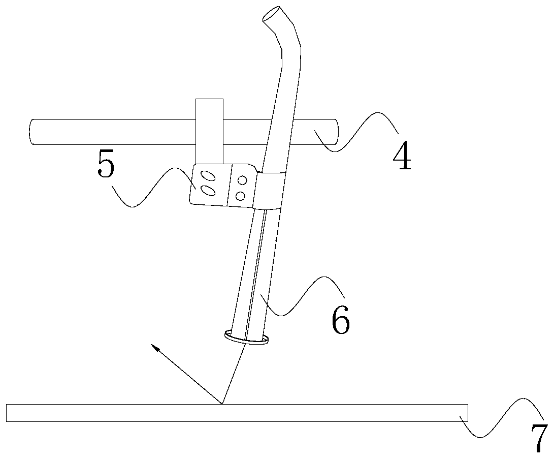
[0027] The nozzle structure is composed of a truss 4, a fixed bracket 5, a nozzle 6, and a CUP board 7. The truss 4 locks the nozzle 6 through the fixed bracket 5, and the nozzle 6 is facing the CUP board 7, and the CUP board 7 ...


PUM


Abstract

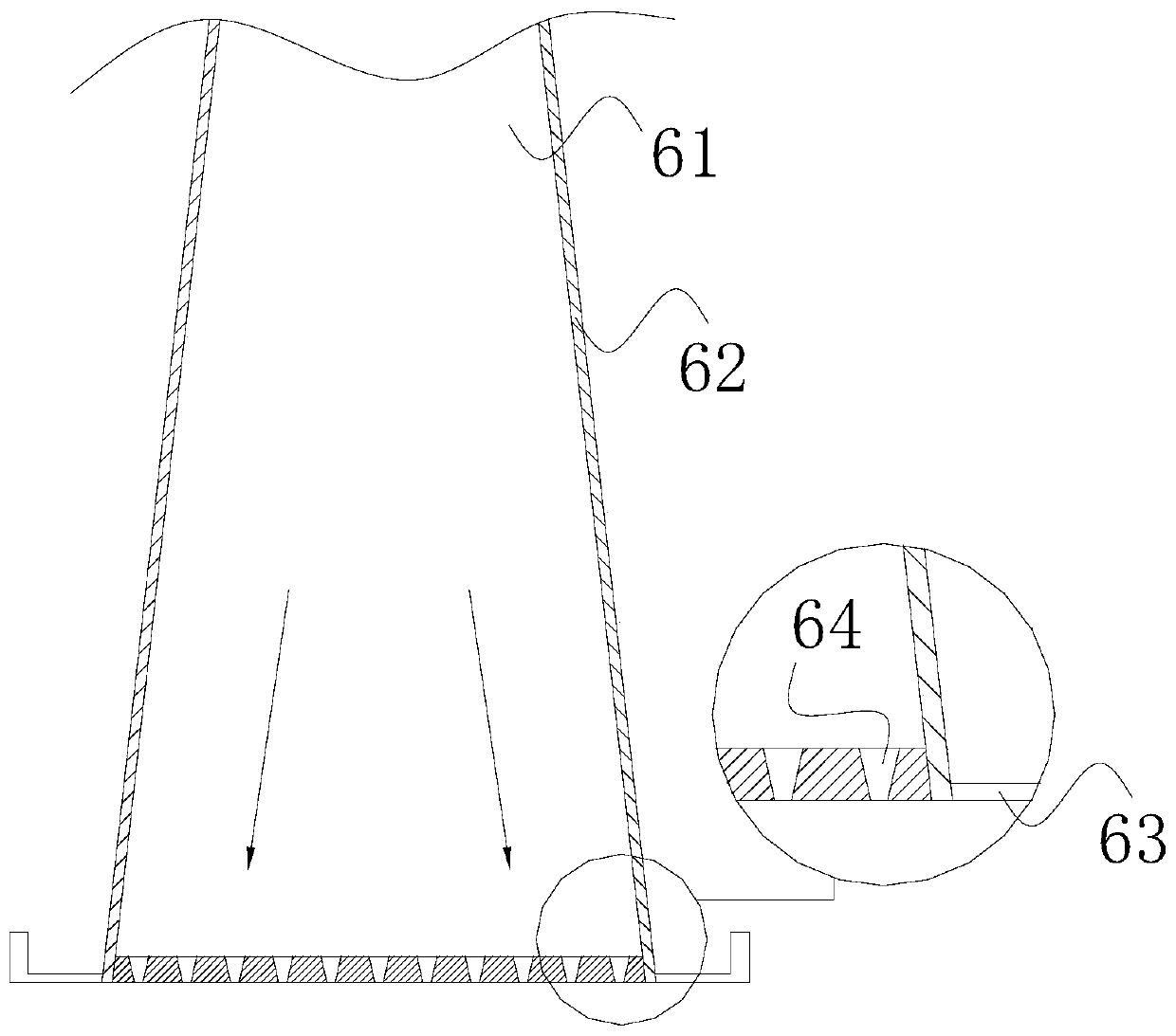
The invention discloses a wafer lithography device. The structure comprises a window, an operation table, a main body, a nozzle structure, a developing tank, an automatic alignment system, a frame vibration reduction system and the like. An operation table is arranged on the main body. The window is arranged on one side of the operation table. A nozzle is arranged inside the main body. The developing tank is arranged at the bottom of the nozzle structure. The automatic alignment system is arranged on the horizontal side of the developing tank. The frame vibration reduction system is arranged directly below the automatic alignment system. The frame vibration reduction system movably matches the developing tank. The nozzle structure is composed of a truss, a fixation bracket, a nozzle and aCPU plate. The truss locks the nozzle through the fixation bracket. The nozzle is directly facing the CPU plate. According to the invention, due to the design of the upper narrow and lower wide structure of a nozzle tube, impurities on the outer surface of the nozzle tube do not contaminate and stay, so as to achieve the purpose of reducing impurities; impurities falling down on the surface are intercepted by an interception disk, and do not be mixed with deionized water from the nozzle; and double ring defects of wafer lithography are directly avoided.

Description

technical field [0001] The present invention relates to the field of wafer lithography equipment, in particular to a wafer lithography equipment. Background technique [0002] Integrated circuit technology is the basic technology required by all electronic products today. The carrier of integrated circuit technology is the integrated circuit board. The most important part of the integrated circuit board is the wafer. The lithography process of wafer manufacturing is the most critical. If Photolithography fails, the wafer is discarded and can no longer be used. Under the action of light, the pattern on the mask plate is transferred to the wafer substrate with the help of photoresist, and the wafer needs to be developed in the developing tank. At this time , when the sprayed deionized water will flow away along the drain pipe, when the wafer is rotated, the impurities containing the ionized water reactant on the spray head controlled by the manipulator will cause backsplash wh...

Claims


Application Information

Patent Timeline
IPC IPC(8): G03F7/30
CPCG03F7/30
Inventor 王斌
Owner 泉州洛江泰润机械科技有限公司
Learn More