Protection board suitable for mounting over-current protection device PTC

A technology of overcurrent protection device and protection board, applied in the field of powerSupply, to achieve the effect of easy action protection and long life

Inactive Publication Date: 2019-12-31
SHANGHAI CHANGYUAN WAYON CIRCUIT PROTECTION CO LTD
View PDF6 Cites 1 Cited by
  • Summary
  • Abstract
  • Description
  • Claims
  • Application Information

AI Technical Summary

Problems solved by technology

[0002] As users' demand for smart phones and other products becomes more and more demanding, the capacity of their batteries is also increasing, and the charging current of mobile phones is also increasing. This kind of fast charging is popular for over-current protection The requirements for device PTC are getting higher and higher. It is expected to reduce the initial resistance, increase the sustainable current, and increase the service life of PTC; however, low resistance will inevitably delay the operation time of PTC. According to the lithium battery safety standard UL2054 Regarding the standard description of LPS, for the occasion where PTC overcurrent protection device is used, the protection action time required by LPS for PTC is 8A and less than 60s
Therefore, only for PTC itself, both low resistance and LPS must be satisfied, which may not be able to meet both

Method used


Image

  • Protection board suitable for mounting over-current protection device PTC
  • Protection board suitable for mounting over-current protection device PTC
  • Protection board suitable for mounting over-current protection device PTC

Examples


Embodiment 1

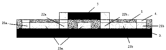
[0040] A protective board suitable for mounting the overcurrent protection device PTC, which only contains one electronic component of PTC 5 and the conductive wire passing through the bottom of the PTC is a test board that passes through all sides on one side, such as figure 1 with figure 2 As shown, it includes a substrate layer 3 and a circuit layer 2. The circuit layer 2 is covered on the surface of the substrate layer 3. The circuit layer 2 includes pads for soldering the pins of each electronic component, conductive wires constituting the circuit, and wires covering the conductive wires. protection layer 1, where,

[0041] Contains a group of pads for welding PTC 5, the first PTC pad 22a, the second PTC pad 22b;

[0042] In this embodiment 1, when the first conductive wire 23a is routed, local wiring is carried out from the middle of the first PTC pad 22a and the second PTC pad 22b where the pins at both ends of the PTC 5 are soldered, that is, it passes through the bo...

Embodiment 2

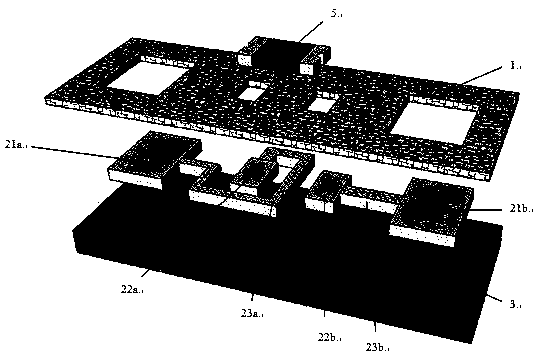
[0048] A protective board suitable for mounting overcurrent protection devices PTC, such as image 3As shown, the conductive wire passing through the bottom of the PTC is a test board with both sides fully passing through, including the substrate layer 3 and the circuit layer 2, the circuit layer 2 covers the surface of the substrate layer 3, and the circuit layer 2 contains soldered electronic components The pads of the pins, the conductive wires constituting the circuit and the protective layer 1 covering the conductive wires, wherein at least one group of first and second PTC pads 22a, 22b for welding PTC 5 are included, the first and second PTC pads 22a, 22b of the present embodiment The second conductive wires 23c and 23d all pass through the middle of the pads where the pins at both ends of the PTC are soldered.

[0049] The only difference between this embodiment and Embodiment 1 is that the routing of the conductive wires is different, such as image 3 As shown, where...

Embodiment 3

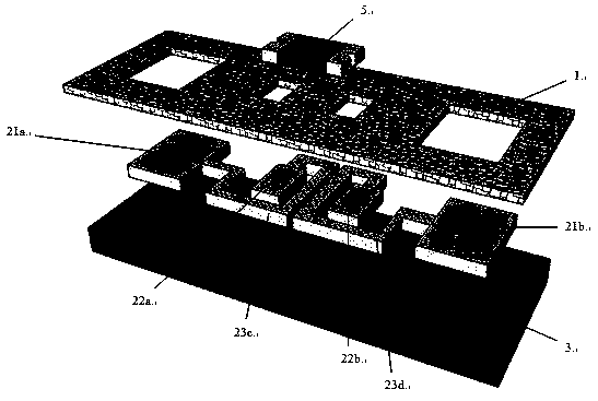
[0052] A protective board suitable for mounting overcurrent protection devices PTC, such as Figure 4 As shown, the conductive wire passing through the bottom of the PTC is a single-sided local wiring type test board, including a substrate layer 3 and a circuit layer 2, and the circuit layer 2 is covered on the surface of the substrate layer 3. The circuit layer 2 includes a group for Solder the pads of the PTC, the conductive wires constituting the circuit and the protective layer 1 covering the conductive wires,

[0053] The only difference between this embodiment and Embodiment 1 is that the routing of the conductive wires is different, such as Figure 4 As shown, wherein the first conductive wire 23e goes out from the side wiring of the first pad 22a where the PTC is welded, then goes out between the first and second PTC pads 22a, 22b, and then connects with the first test pad 21a ; The second conductive line 23f is directly connected to the second test pad 21b.

[0054]...


PUM


Abstract

The invention relates to a protection board suitable for mounting an over-current protection device PTC. The protection board is a hard board, a soft board and a rigid-flexible board. The protection board comprises a substrate layer and a circuit layer, wherein the circuit layer covers a surface of the substrate layer, the circuit layer comprises bonding pads for welding pins of electronic components, conductive wires forming a circuit, and a protective layer covering the conductive wires, the conductive wire at least comprises one group of bonding pads for welding the PTC, and at least one conductive wire performs local wiring from the middle of bonding pads of welding pins at two ends of the PTC or penetrates through the bonding pads of the pins at two ends of the PTC during wiring, i.e., the at least one conductive wire passes through the bottom of the PTC. The protection board is advantaged in that the conductive wire passes through the bottom of the PTC during wiring, when the current is small, the section of the conductive wire generates little heat, the PTC is hardly influenced by the heat of the section of the conductive wire, and when the current is large, the section of the conductive wire generates dramatically increased heat, the PTC is greatly influenced by the heat of the section of the conductive wire, and the action protection of the PTC is more easily triggered.

Description

technical field [0001] The present invention relates to a protection board that can not only ensure the long-term use of PTC under the usual low current application conditions, but also meet the requirement of a limited power supply (Limited Power Supply, LPS for short) 8A protection action time within 60s. By designing the wiring to pass between the pads soldering the pins at both ends of the PTC, that is, passing through the bottom of the PTC, when a small current is passed, the conductive wire generates little heat and hardly affects the PTC; when a large current is passed At this time, the section of the conductive wire generates a lot of heat, which accelerates the heating of the PTC and makes it easier for the PTC to operate for protection. Background technique [0002] As users' demand for smart phones and other products becomes more and more demanding, the capacity of their batteries is also increasing, and the charging current of mobile phones is also increasing. Th...

Claims


Application Information

Patent Timeline
Patent Type & Authority Applications(China)
IPC IPC(8): H05K1/02H05K1/18H01C1/14H01C7/02
CPCH05K1/0296H05K1/181H01C1/14H01C7/02H05K2201/10022
Inventor 夏坤方勇张锐黄定兵曹清华张伟吴国臣
Owner SHANGHAI CHANGYUAN WAYON CIRCUIT PROTECTION CO LTD
Why Eureka
Try Eureka