Optical fiber composite light spot laser beam combiner and manufacturing method thereof

A laser beam combiner and optical fiber composite technology, which is applied in manufacturing tools, laser welding equipment, welding equipment, etc., can solve the problems of high cost, inability to modulate, and reduce the reliability of optical fibers, so as to save costs, improve reliability, The effect of reducing internal porosity in welding

Pending Publication Date: 2020-01-03
NANJING FIBER FOTON TECH CORP LTD
View PDF6 Cites 4 Cited by
  • Summary
  • Abstract
  • Description
  • Claims
  • Application Information

AI Technical Summary

Problems solved by technology

However, the spot quality and spot shape output by fiber lasers currently on the market are mostly fixed and cannot be adjusted. If only a single laser device is used, it will not be able to meet all processing requirements. Therefore, the adjustable spot in the laser will be A solution to this problem
[0004] There are three main ways to adjust the spot on the market. The first way is to install a spot modulator composed of optical lenses on the outside of the fiber laser to convert the quasi-single-mode spot into a flat-top spot. However, the lens group is easily affected by time and The impact of vibration causes lens shift to affect the reliability of the laser; the second method is to use two lasers to output two lasers with different wavelengths and different spots, and then use a composite processing head to combine the two lasers to achieve modulation effect, but this method requires two laser equipment and a composite processing head, and the cost is high; the third method is to bend the fiber in the fiber laser, so that the laser is coupled from a single mode to a high mode in the fiber, borrowing This achieves the effect of modulating the spot, but the fiber is prone to reduce the reliability of the fiber itself under repeated force bending, which eventually leads to damage to the laser
[0005] The biggest challenge in the current laser welding operation is when tailor-welding galvanized steel sheets, because the melting point of zinc is low, it is easy to form spatter and pores during the welding process, which greatly reduces the strength and reliability of the weld
Therefore, how to reduce the porosity of the weld seam during the laser welding process, and at the same time, the equipment has the advantages of high reliability and low cost, and can achieve the function of outputting different light spots with a single laser equipment. major challenges to popularization

Method used


Image

  • Optical fiber composite light spot laser beam combiner and manufacturing method thereof
  • Optical fiber composite light spot laser beam combiner and manufacturing method thereof
  • Optical fiber composite light spot laser beam combiner and manufacturing method thereof

Examples


Embodiment

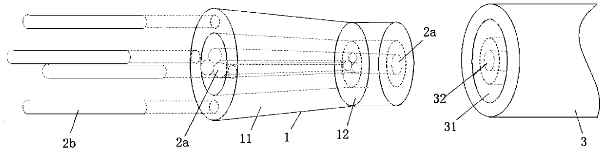
[0032] refer to figure 1 As shown, the present embodiment is an optical fiber composite spot laser beam combiner, which includes a hollow tapered tubular glass waveguide, several outer ring input optical fibers 2b uniformly welded on the section of the tube wall 11 of the tubular glass waveguide 1, and a beam combiner A number of central input optical fibers 2a placed in the center of the tubular glass waveguide 1, and a large mode field optical transmission optical fiber 3 located at the tapered end of the tube wall of the tubular glass waveguide and fused and condensed;

[0033] The large mode field optical transmission fiber 3 includes a ring-type waveguide connection end 31 corresponding to the tapered end of the tube wall 11 of the tubular glass waveguide 1, and correspondingly matched with the central input optical fiber 2a bundled at the center of the tubular glass waveguide 1 The connection fiber 32.

[0034] A number of central input optical fibers 2a combine the inp...


PUM


Abstract

The invention discloses an optical fiber composite light spot laser beam combiner. The optical fiber composite light spot laser beam combiner comprises a hollow tubular glass waveguide formed throughtapering, multiple outer ring input optical fibers evenly distributed and welded to the section of the tube wall of the tubular glass waveguide, multiple central input optical fibers arranged on the center of the tubular glass waveguide in a beam combining manner, and a large-mold-field optical transmission optical fiber located on the tube wall tapering end of the tubular glass waveguide and welded and condensed. The tube wall of the tubular glass waveguide, the input laser on the center position of the waveguide and the output laser of the large-mold-field optical transmission optical fiberare effectively coupled to form the composite light spots. The combiner has the advantages that the same laser device can modulate the light spot quality and the light spot form, and can be applied todifferent laser machining applications, and the efficiency of the same laser in the different applications at the same time can be improved.

Description

technical field [0001] The invention belongs to the technical field of laser equipment, in particular to an optical fiber composite spot laser beam combiner and a manufacturing method thereof. Background technique [0002] Fiber lasers have the advantages of high performance, high efficiency, high reliability, and low cost. Low power consumption and high reliability are important factors for cost savings of fiber lasers. Therefore, in the past few decades, fiber lasers have been used in industrial materials The processing market is developing rapidly. The main fiber laser application industries include laser welding, laser cutting, laser additive manufacturing, laser quenching and cladding, etc. [0003] In the processing application of fiber laser, the spot quality of laser output plays an important role, which determines the quality of processing. In laser cutting applications, it is suitable to use single-mode laser spot for thin plate cutting, flat-top laser spot for t...

Claims


Application Information

Patent Timeline
Patent Type & Authority Applications(China)
IPC IPC(8): B23K26/06
CPCB23K26/0665
Inventor 马吉德·伊姆蒂亚兹王志豪黄昭文
Owner NANJING FIBER FOTON TECH CORP LTD
Why Eureka
Try Eureka