Supercharge Your Innovation With Domain-Expert AI Agents!

Sucker rod with oil pipe traction device and casing

A technology of traction device and sucker rod, which is applied in the direction of casing, drill pipe, drill pipe, etc., can solve the problem of low oil yield, achieve the effect of increasing oil yield and expanding oil production area

Inactive Publication Date: 2020-01-03
左入林
View PDF9 Cites 0 Cited by
  • Summary
  • Abstract
  • Description
  • Claims
  • Application Information

AI Technical Summary

Problems solved by technology

[0003] In view of the deficiencies in the prior art, the object of the present invention is to provide a sucker rod with a tubing traction device, which solves the problem of low oil yield when the oil well deviates from the center of the oil pit

Method used


Image

  • Sucker rod with oil pipe traction device and casing
  • Sucker rod with oil pipe traction device and casing
  • Sucker rod with oil pipe traction device and casing

Examples


Embodiment 1

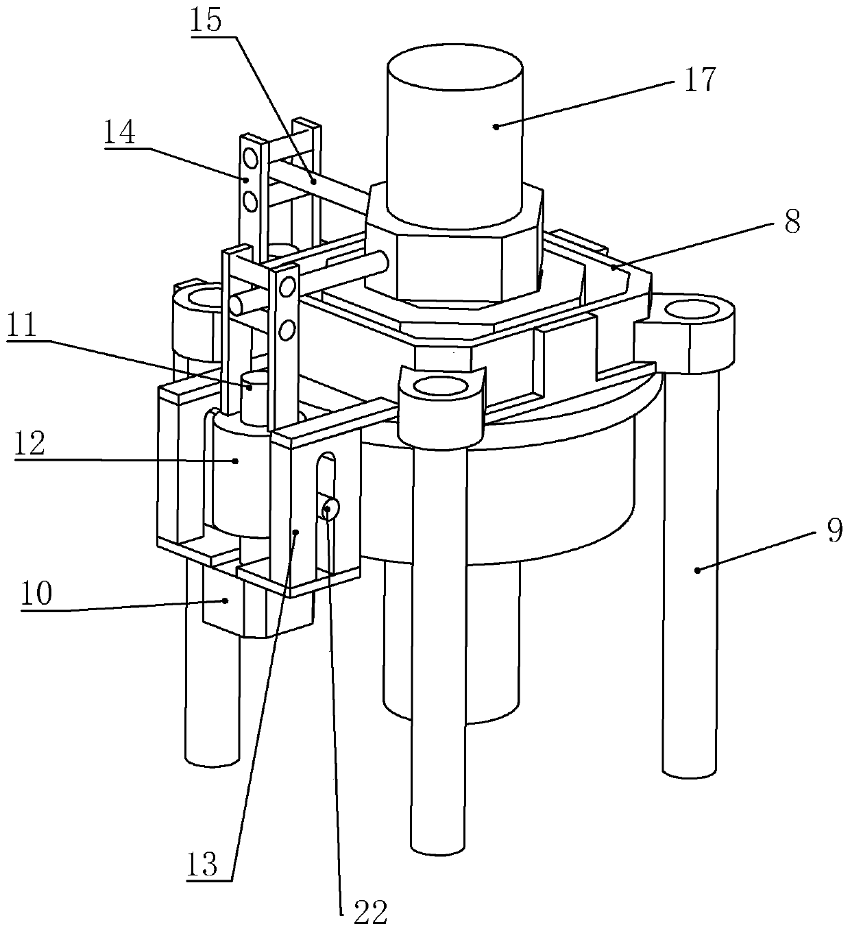
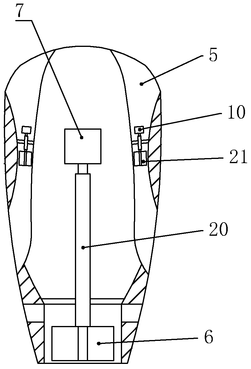
[0029] The steering mechanism includes a mounting base 8, a gyroscope, an X-axis steering assembly and a Y-axis steering assembly. The bottom of the mounting base 8 is provided with a strut 9, and is suspended at the center of the housing 5 in the forward direction by the strut 9. The link 20 is fixed at the center of the mount 8 by a gyroscope, the X-axis steering assembly and the Y-axis steering assembly are arranged on both sides adjacent to the mount 8, and the X-axis steering assembly includes an azimuth motor 10, a screw 11, and a screw sleeve 12 , limit bracket 13, jacket 14 and cross bar 15, one end of cross bar 15 is connected on the connecting rod 20, azimuth motor 10 and limit bracket 13 are fixed on the mount 8, and one end of screw mandrel 11 is connected with azimuth motor 10 The output shaft is fixedly connected, the other end is threadedly connected with the screw sleeve 12, the outer peripheral surface of the screw sleeve 12 is provided with a limit rod 22, the...

Embodiment 2

[0032] Through holes are respectively arranged around the housing 5 , and a steering mechanism is provided in each through hole. The steering mechanism includes an azimuth motor 10 and a steering turbine 21 , and the steering turbine 21 is connected to the output shaft of the azimuth motor 10 . In this embodiment, the effect of changing the orientation is achieved by adding power assistance to the side of the housing 5. When the housing 5 moves in the horizontal direction, the housing 5 needs to move upwards, and the azimuth motor 10 below the housing 5 starts to drive the steering turbine 21 to rotate. , so as to push the housing 5 to move upwards, the housing 5 needs to be moved downwards, and the azimuth motor 10 above the housing 5 starts to drive the steering wheel 21 to rotate, pushing the housing 5 to move downwards.

Embodiment 3

[0034]The housing 5 is respectively provided with a rotatable side wing on both sides near the tail, and the top of the housing 5 is provided with a rotatable ridge wing. The steering mechanism includes two side wing motors and a ridge wing motor, and the side wing is provided with a side wing shaft. , the other end of the wing rotating shaft is fixedly connected with the output shaft of the wing motor, the ridge wing is provided with a ridge wing rotating shaft, and the other end of the ridge wing rotating shaft is fixedly connected with the output shaft of the ridge wing motor. This embodiment utilizes the principle of an airplane wing to achieve the effect of changing the moving direction of the housing 5 by changing the direction of the side wings or ridge wings. Both the wing motor and the side wing motor use servo motors, and the control accuracy is high.

[0035] The casing 5 is provided with a storage battery, which is electrically connected to the motor, and the storag...


PUM


Abstract

The invention discloses a sucker rod with an oil pipe traction device and a casing. The sucker rod includes an inner pipe, the bottom of the inner pipe is provided with a receiving disc, the receivingdisc is provided with a plurality of connection holes, an oil pipe is connected into each connection hole, and the traction device is connected to the other ends of the oil pipes; the traction deviceincludes a housing, a pushing mechanism and a steering mechanism, the pushing mechanism and the steering mechanism are arranged in the housing, the pushing mechanism is used for pushing the housing forwards to disperse the oil pipes, and the steering mechanism is used for changing the moving direction of the housing; the casing comprises a hollow pipe, a chuck and a center rod, the chuck and thecenter rod are arranged in the hollow pipe, the chuck is in threaded connection to the center rod and is arranged near the bottom end of the center rod, an electromagnet for attaching the traction device is connected to the bottom wall of the center rod, one end of each oil pipe is connected to the chuck, the chuck is threaded connection to the receiving disc, the thread direction of the center rod is opposite to that of the receiving disc, the chuck is provided with a rotating mechanism for automatic rotation of the chuck, the oil pipes are installed on the inner pipe through the casing, andconnection is relatively simple.

Description

technical field [0001] The present invention relates to a mining machine, and more particularly, it relates to a sucker rod and casing with a tubing pulling device. Background technique [0002] It is necessary to drill multiple oil wells in the oil field because the oil is in the underground rock crevices. After the oil in the oil pit is exploited, it is necessary to choose a new location to drill the well again, and because the exploration of the oil pit is more difficult. A lot of waste wells are often drilled. Even the oil wells that produce oil have different positions where the wellhead is located in the oil pit. Sometimes the position deviates greatly from the center of the oil pit, and the oil yield will be low, and the cost of re-drilling the well is high. Contents of the invention [0003] In view of the deficiencies in the prior art, the object of the present invention is to provide a sucker rod with a tubing pulling device, which solves the problem of low oil y...

Claims


Application Information

Patent Timeline
IPC IPC(8): E21B17/00E21B17/02E21B23/00E21B19/10E21B47/06
CPCE21B17/00E21B17/021E21B19/10E21B23/00E21B47/06
Inventor 左入林左韬
Owner 左入林
Features
  • R&D
  • Intellectual Property
  • Life Sciences
  • Materials
  • Tech Scout
  • Unparalleled Data Quality
  • Higher Quality Content
  • 60% Fewer Hallucinations
Learn More