High-gain Boost converter

A converter and high-gain technology, applied in the electrical field, can solve the problems of parasitic capacitance, large power tube and capacitor voltage stress, and low overall efficiency, so as to reduce on-state loss and cost, avoid reverse recovery loss, and on-state The effect of wastage avoidance

Active Publication Date: 2020-01-03
NANTONG UNIVERSITY
View PDF6 Cites 6 Cited by
  • Summary
  • Abstract
  • Description
  • Claims
  • Application Information

AI Technical Summary

Problems solved by technology

Among them, isolated converters or boost converters with coupled inductors have problems such as bulky size, high cost, leakage inductance and parasitic capacitance; Boost converter cascaded systems have two-stage energy conversion, the overall efficiency is low, and the topology and Stability design is more complex
and figure 1 The secondary boost converter shown has the same gain as the cascaded boost converter, and the number of switch tubes is reduced, which reduces the difficulty of system control, but the number of diodes is large, and the voltage stress of power tubes and capacitors Both are large, which increases the difficulty and cost of device selection

Method used


Image

  • High-gain Boost converter
  • High-gain Boost converter
  • High-gain Boost converter

Examples


Embodiment Construction

[0023] The following will clearly and completely describe the technical solutions in the embodiments of the present application with reference to the accompanying drawings in the embodiments of the present application. Obviously, the described embodiments are only part of the embodiments of the present application, not all of them. Based on the embodiments in this application, all other embodiments obtained by persons of ordinary skill in the art without making creative efforts fall within the protection scope of the present invention.

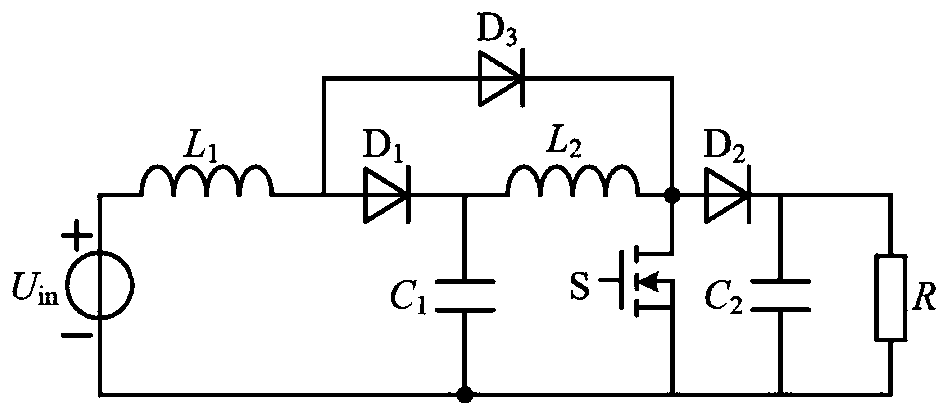
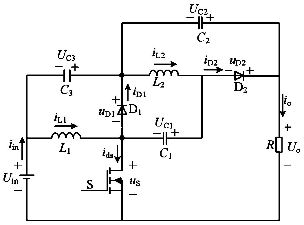
[0024] Please refer to figure 2 , figure 2 A schematic diagram of a circuit structure of a high-gain Boost converter provided by an embodiment of the present invention. The high-gain Boost converter includes a DC voltage source U in , the first inductance L 1 , the second inductance L 2 , switch tube S, first diode D 1 , the second diode D 2 , the first capacitance C 1 , the second capacitance C 2 , the third capacitor C 3 and the l...


PUM


Abstract

The invention discloses a high-gain Boost converter which comprises a direct-current voltage source, a switching tube, a first diode, a second diode, a first inductor, a second inductor, a first capacitor, a second capacitor, a third capacitor and a load. The voltage gain of the high-gain Boost converter is G=(1+D) / (1-D), and higher voltage gain can be achieved under the condition of lower duty ratio. The voltage stresses of all power devices are (Uin+Uo) / 2, and the voltage stresses of all the capacitors are (Uo-Uin) / 2. Compared with a traditional quadratic Boost converter, the voltage stresses of the switching tube, part of the diodes and the capacitors of the high-gain Boost converter of the invention are reduced to a certain extent under the same working condition, the number of diodesis reduced by one, the system loss, the device model selection difficulty and the device model selection cost are reduced, and the conversion efficiency is improved. The high-gain Boost converter is suitable for application occasions requiring medium boosting capability (the voltage gain G is less than or equal to 9), such as a single-phase UPS and a direct-current micro-grid.

Description

technical field [0001] The present application relates to the field of electrical technology, in particular to a high-gain Boost converter. Background technique [0002] With the gradual depletion of traditional fossil energy, and the increasingly serious problems of environmental pollution and global warming, the development and utilization of new energy with the characteristics of wide distribution of resources, great development potential, small environmental impact, and sustainable use has become more and more popular. people's attention. At present, the new energy power generation systems that are widely used mainly include photovoltaic, wind power, and fuel cell power generation. The output voltage of photovoltaic modules, fuel cells, batteries and other modules is relatively low, generally 30-48V, while the input voltage required by half-bridge / full-bridge grid-connected inverters is usually above 380 / 760V. Connecting multiple photovoltaic cell modules or fuel cells...

Claims


Application Information

Patent Timeline
Patent Type & Authority Applications(China)
IPC IPC(8): H02M3/07
CPCH02M3/07H02M1/0048H02M1/0051Y02B70/10
Inventor 秦岭张宇妍周磊韩启萌田民尹铭沈家鹏高娟段冰莹
Owner NANTONG UNIVERSITY
Why Eureka
Try Eureka