Multi-mode control method of active clamp fly-back converter

A flyback converter and control method technology, applied in control/regulation systems, conversion of DC power input to DC power output, instruments, etc., can solve the problem of low light-load efficiency, poor electromagnetic interference characteristics, and large primary peak current. and other problems, to achieve the effect of improving light load efficiency, avoiding audio noise, and small circulating current

Active Publication Date: 2020-01-03
MORNSUN GUANGZHOU SCI & TECH
View PDF11 Cites 13 Cited by
  • Summary
  • Abstract
  • Description
  • Claims
  • Application Information

AI Technical Summary

Problems solved by technology

This patent realizes switching between complementary mode, common flyback and burst mode by detecting the voltage of the feedback pin FB. However, the complementary mode has an advantage at a power level above 45W, because if the power is too small, when working in complementary mode The circulating current is still very large, which causes the converter to have no advantage at low power levels
And as the load decreases, the switching frequency will increase in the complementary mode, which will cause a large jump in the operating frequency when the mode is switched, resulting in loop instability and poor electromagnetic interference (EMI) characteristics
When the light load works in the traditional discontinuous flyback (DCM) mode, the energy stored in the clamp capacitor can only be consumed by connecting a large resistor in parallel, so the light load efficiency is not high
[0012] The patent US10243469B1 provides a burst mode control method, which works in the normal flyback burst mode when the load is less than 20%. In this mode, the energy stored on the clamp capacitor can only be connected in parallel with a large Resistor to consume; it also works in complementary mode at full load, so it is only suitable for products with higher power levels
[0013] Patent CN101572490A proposes a non-complementary control method. Although the frequency of this control method can be reduced as the load decreases, the negative current still exists, resulting in low efficiency of the converter with large circulating current and light load. At the same time, the negative current Existence makes the peak current of the primary side relatively large, resulting in relatively large no-load power consumption and audible noise

Method used


Image

  • Multi-mode control method of active clamp fly-back converter
  • Multi-mode control method of active clamp fly-back converter
  • Multi-mode control method of active clamp fly-back converter

Examples


Embodiment Construction

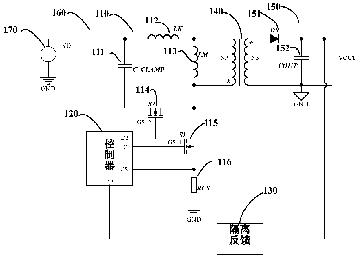
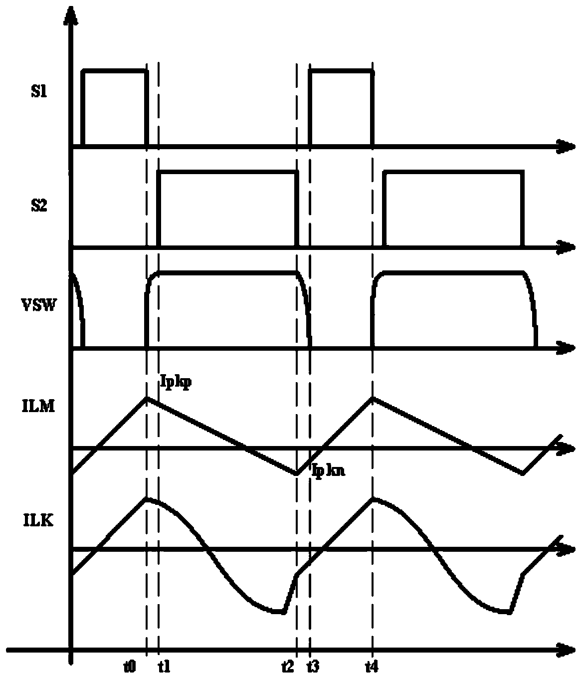
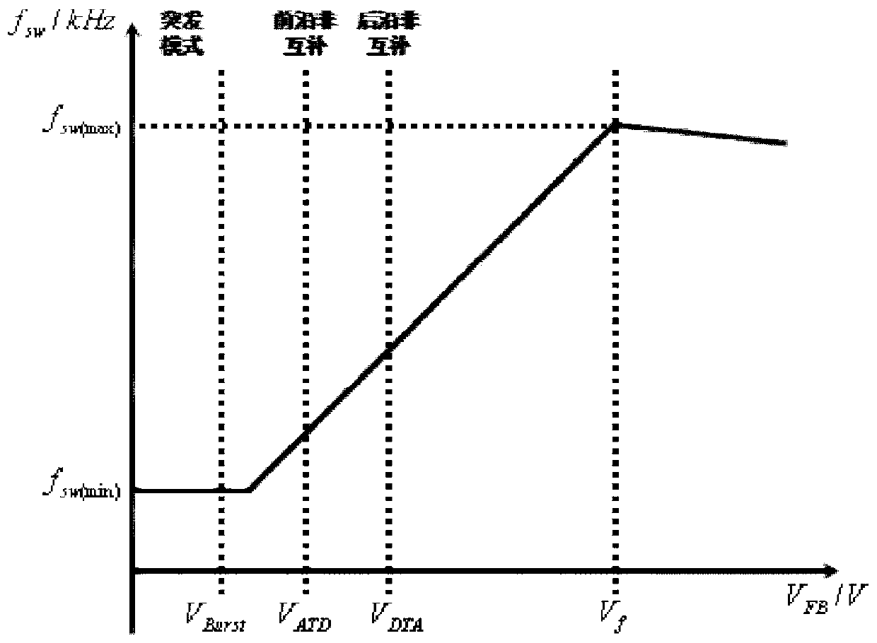
[0036] In one embodiment, a multi-mode flyback power supply includes an active clamp flyback converter and a controller. The active clamp flyback converter is used to adjust the input voltage and output the desired voltage. The active clamp flyback converter includes the main switch tube that controls the current of the primary winding of the flyback transformer, and the primary side of the flyback transformer The clamp switch tube for clamping the node voltage. The controller generates control signals for controlling the main switch and the clamp switch by detecting the FB voltage. The multi-mode flyback power supply can operate in trailing edge non-complementary mode, leading edge non-complementary mode and leading edge non-complementary burst mode (Burst mode ) These existing patterns combine to drive work. Among them, the switching frequency of the trailing edge non-complementary mode and the leading edge non-complementary mode changes with the change of the FB voltage. ...


PUM


Abstract

The invention provides a multi-mode control method of an active clamp fly-back converter. In the fly-back converter, a controller realizes mode switching among a lagging edge non-complementary mode, aleading edge non-complementary mode and a leading edge non-complementary Burst mode of two driving signals after detecting a feedback voltage and comparing the feedback voltage with a set mode switching threshold voltage. According to the invention, the lagging edge non-complementary mode is adopted to reduce the circulating current of the converter, the leading edge non-complementary mode is adopted instead of a common fly-back mode to improve the light-load efficiency, and the leading edge non-complementary burst mode is adopted under the condition of no load in order to limit the magnitudeof the primary peak current in the burst mode, avoid audio noise and achieve low no-load power consumption.

Description

technical field [0001] The invention relates to a control method of a flyback converter, in particular to a multi-mode control method of an active clamp flyback converter. Background technique [0002] Flyback converters are widely used in small and medium power switching power supplies because of their low cost and simple topology. In the actual working process, due to the existence of the leakage inductance of the flyback converter, the energy of the primary side cannot be completely transferred to the secondary side, and the resonance between the leakage inductance energy left on the primary side and the junction capacitance of the MOS tube causes the drain of the main switch tube Generate high frequency voltage spikes. In order to reduce the voltage stress of the switch tube when making products, it is common practice to add suitable snubber circuits. Common snubber circuits include RCD snubber circuits, LCD snubber circuits and active clamp circuits. Among them, the a...

Claims


Application Information

Patent Timeline
Patent Type & Authority Applications(China)
IPC IPC(8): H02M3/335
CPCH02M3/33569H02M3/33507H02M1/0006H02M1/0058H02M3/33523H02M1/0035H02M1/342H02M1/44Y02B70/10
Inventor 尹向阳王海洲袁源刘湘
Owner MORNSUN GUANGZHOU SCI & TECH
Why Eureka
Try Eureka