Environment-friendly cement packing machine

A packaging machine and cement technology, which is applied in packaging, transportation and packaging, and the type of packaged items. It can solve the problems of low production capacity and poor output effect of cement packaging machines, so as to improve filling efficiency, production capacity, time and The effect of less energy consumption

Active Publication Date: 2020-01-07
冀东水泥重庆合川有限责任公司
View PDF11 Cites 4 Cited by
  • Summary
  • Abstract
  • Description
  • Claims
  • Application Information

AI Technical Summary

Problems solved by technology

[0003] The present invention intends to provide an environment-friendly cement packaging machine to solve the problem of low production capacity of the cement packaging machine due to the poor discharge effect of the prior art during filling

Method used


Image

  • Environment-friendly cement packing machine
  • Environment-friendly cement packing machine
  • Environment-friendly cement packing machine

Examples


Embodiment 1

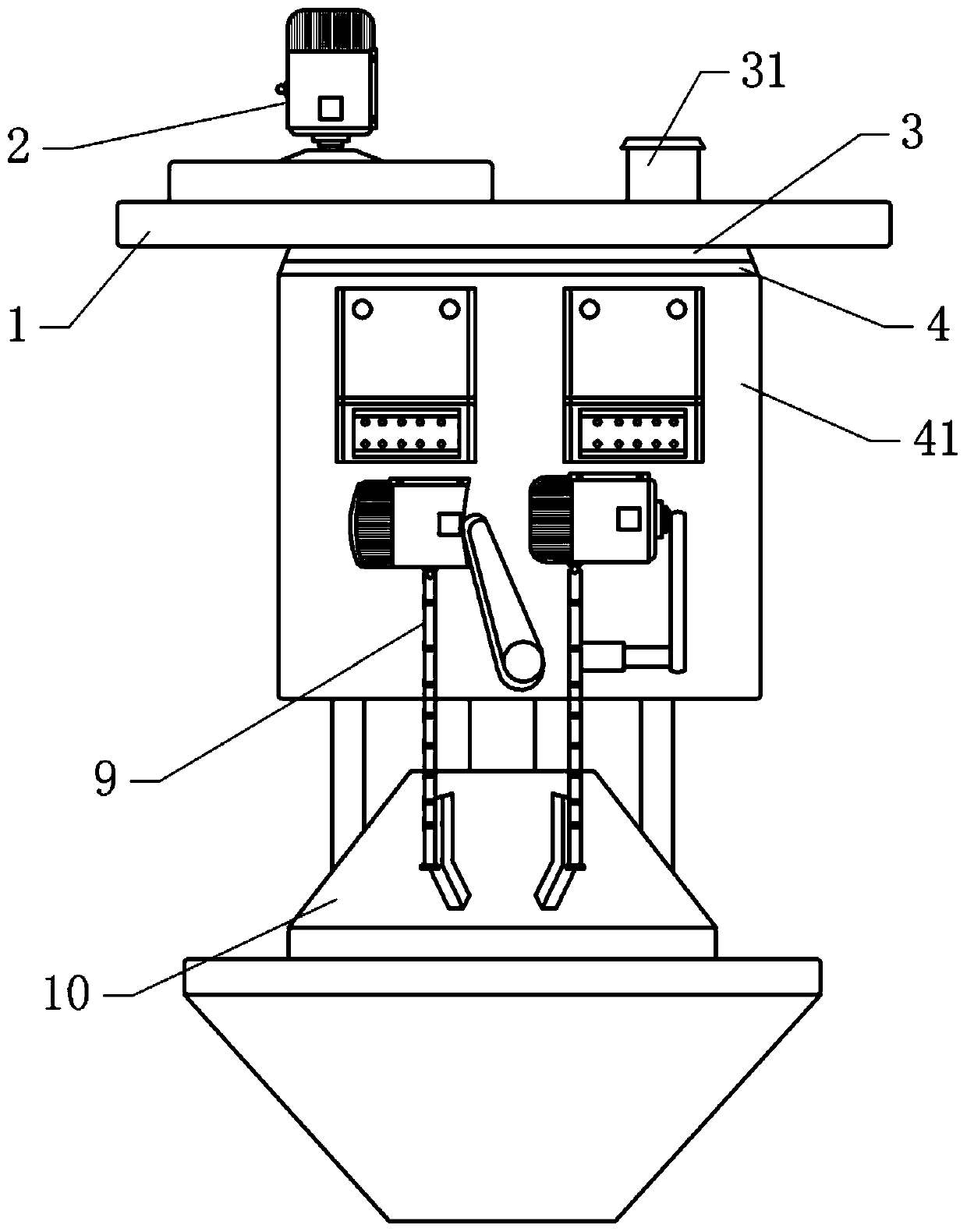
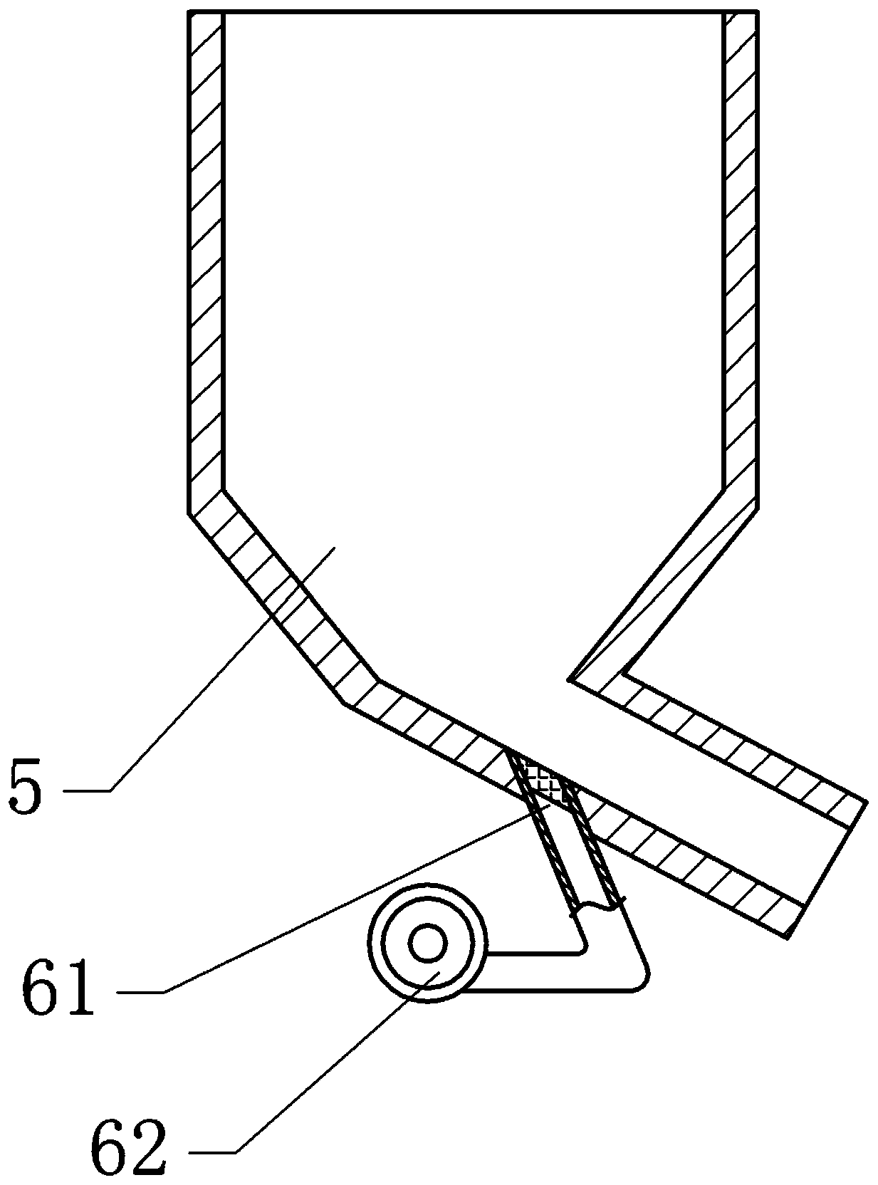
[0036] as attached figure 1 As shown, the environmentally friendly cement packaging machine is basically like the BHYW8D rotary cement packaging machine, including a suspension beam, a power system 2 is fixed above the suspension beam 1, and the power system 2 is a motor. Below the suspension beam hanger 1 are sequentially provided an upper cover 3 device, an upper rotary body, a filling system, a bagging mechanism, a switch smashing mechanism, a lower rotary body, and a microcomputer scale. There is a feeding cylinder 31, the upper rotating body includes a connecting plate 4 fixed with the upper cover 3, and a storage bin 41 communicating with the feeding cylinder 31 is fixed on the connecting plate 4; figure 2 As shown, the filling system includes an ash hopper 5 communicated with the storage bin 41 and a ventilation system 6 communicated with the ash outlet of the ash hopper 5; the bagging mechanism includes a bagging rack 9 fixed on the storage bin 41 , the ash outlet co...

Embodiment 2

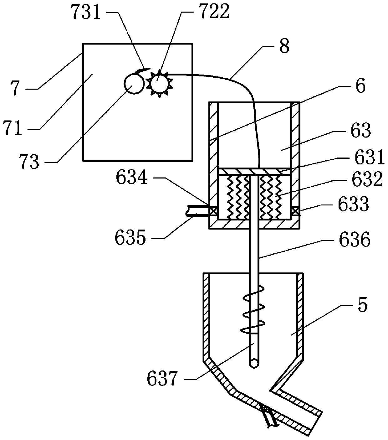
[0041] The difference between this embodiment and Embodiment 1 is that, as shown in the appendix image 3 As shown, the ventilation system 6 includes an air storage cylinder 63 fixed at the bottom of the storage bin 41, the bottom end of the air storage cylinder 63 is closed, a sliding plate 631 is vertically slidably connected in the air storage cylinder 63, and a sliding plate 631 is welded between the bottom of the sliding plate 631 and the bottom of the air storage cylinder 63. Spring 632. An air inlet 633 and an air outlet 634 are arranged on the side wall of the air storage cylinder 63 under the sliding plate. The air inlet 633 is provided with an air inlet one-way valve. When the sliding plate 631 moves up, the gas pressure at the lower part of the air storage cylinder 63 decreases. , the external air is sucked through the air inlet 633; ​​the air outlet 634 is provided with an air outlet check valve, when the slide plate 631 moves down, the gas in the air storage cylin...

Embodiment 3

[0047] The only difference between this embodiment and Embodiment 2 is that, such as Figure 5 As shown, the driving mechanism 7 includes a pulley 74 and a rotating wheel 75 that are rotatably connected to the fixed plate 71. The pulley 8 is wound on the pulley 74 to form a fixed pulley 74 structure, and a ratchet rack 76 is fixed at one end of the pulley 8 away from the sliding plate 631. , the fixed plate 71 is provided with a vertical sliding groove, and the ratchet rack 76 is provided with a slider that cooperates with the sliding groove, so that the ratchet rack 76 can slide vertically along the sliding groove, and the rotating wheel 75 is provided with a 1 A pawl 731 that cooperates with the ratchet rack 76 .

[0048] The specific use process is as follows:

[0049] The rotating wheel 75 rotates, so that the pawl 731 intermittently cooperates with the ratchet rack 76, so that the ratchet rack 76 can drive one end of the pull rope 8 to move down, and the other end of the...


PUM


Abstract

The invention belongs to the technical field of powdery material packing and conveying and discloses an environment-friendly cement packing machine. The environment-friendly cement packing machine comprises a suspension beam, a power system is arranged above the suspension beam, and an upper cover device, an upper rotation body, a filling system, a bagging mechanism, an open-close plate breaking mechanism, a lower rotation body and a microcomputer weighing scale are arranged below the suspension beam in sequence; the open-close plate breaking mechanism comprises a power supply, an electromagnet connected with the power supply and a plate breaking electromagnet capable of controlling the power supply to be connected and disconnected and used for controlling a pressure bag rubber wheel to move; the lower rotation body comprises a connection cylinder fixed to a connection disc, a conical disc fixed to the lower portion of the connection cylinder and a lower supporting column fixed betweenthe conical disc and a storage bin; the microcomputer weighing scale is fixed to the bottom of a bagging rack. The environment-friendly cement packing machine can achieve automatic filling, weighingand bag removal on cement, the cement can be subjected to flow guide through a ventilation system and is prevented from blocking an ash outlet of an ash outlet hopper, the filling efficiency is improved accordingly, energy consumption is reduced, and the functions of saving energy and protecting the environment are achieved.

Description

technical field [0001] The invention belongs to the technical field of packaging and conveying of powdery materials, and in particular relates to an environment-friendly cement packaging machine. Background technique [0002] Cement is a powdery hydraulic inorganic cementitious material, which can harden in water and firmly bond sand, stone and other materials together, so it is often used in civil construction, water conservancy, national defense and other projects. Since cement is in powder form, it needs to be packaged for convenience, transportation, sale and use. As a special equipment for cement packaging, cement packaging machine is usually used for the packaging of cement or other powdery materials (such as coal ash, various additives, etc.). When the cement is being packed, the accumulation of materials in the silo is large, and the upper material will compact the lower material, resulting in poor discharge effect of the silo, which in turn leads to low production ...

Claims


Application Information

Patent Timeline
Patent Type & Authority Applications(China)
IPC IPC(8): B65B1/06B65D88/70B65B1/32B65B1/28
CPCB65B1/06B65B1/28B65B1/32B65D88/703
Inventor 董保军房浩李明凯张建苏炜炜
Owner 冀东水泥重庆合川有限责任公司
Why Eureka
Try Eureka