Device for removing CO2 from European smelting furnace gas

A technology for coal gas and shaft furnaces, which is applied in the direction of combustible gas purification/transformation, combustible gas purification, and reduction of gas emission, etc. , the effect of solving gas shortage

Pending Publication Date: 2020-01-07
XINJIANG BAYI IRON & STEEL
View PDF0 Cites 1 Cited by
  • Summary
  • Abstract
  • Description
  • Claims
  • Application Information

AI Technical Summary

Problems solved by technology

At this stage, the utilization of Ouyeel furnace gas to reduce fuel consumption mainly has the following disadvantages: (1) Ouyeel furnace has passed the three-year industrial test in Bayi Iron and Steel Co., Ltd., and various indicators have stabilized, and the fuel consumption has remained at about 850Kg / t, and no breakthrough has been made. , there is an urgent need to reduce fuel consumption through technological innovation and reduce CO from the source 2 emission
However, the existing emission reduction methods are limited, and it is urgent to find a new technology to further reduce fuel consumption and reduce ironmaking costs
(2) Waste of calorific value of excess gas and top gas
In winter, under the economic operation mode, the output of blast furnace (BF) is low, and the amount of gas generated is small. There is a large amount of gas, but there is no demand for heating, so the gas is forced to be released in large quantities, and energy is wasted

Method used


Image

  • Device for removing CO2 from European smelting furnace gas

Examples


Embodiment Construction

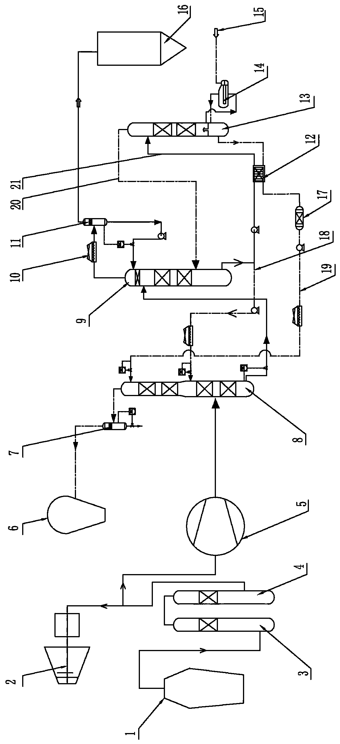
[0010] A Ouyeel Furnace Gas Removal of CO 2 devices such as figure 1 As shown, it includes a shaft furnace 1 with a top gas output pipe, a washing and cooling tower 3, a water-gas separator 4, a high-pressure gas residual pressure turbine power generation device TRT 1, a compressor 5, a gasifier 6, an absorption tower 8, and a normal Decomposition tower 9, stripper 13, cooler, reboiler 14, separator and coal injection device 16, the top gas output pipe of shaft furnace 1 passes through washing cooling tower 3, water-gas separator 4 and described TRT successively 1 and the compressor 5 are connected, the gas output end of the compressor 5 is connected with the bottom of the absorption tower 8, and the top of the absorption tower 8 is connected with the gasification furnace 6 through a purified gas separator 7; the bottom of the absorption tower 8 is provided with Liquid outlet pipe, this liquid outlet pipe links to each other with the top of normal solution tower 9. The top o...


PUM


Abstract

The invention discloses a device for removing CO2 from European smelting furnace gas, which is characterized in that a top gas output pipe of a shaft furnace is connected with a TRT and a compressor sequentially through a washing and cooling tower and a water-gas separator, the gas output end of the compressor is connected with the lower part of an absorption tower, and the top of the absorption tower is communicated with a gasification furnace; a liquid outlet pipe is arranged at the bottom of the absorption tower and is connected with the upper part of a normal solution tower, the top end ofthe normal solution tower is communicated with a coal injection device through a regenerated gas separator, and a return pipe connected with the upper end of the normal solution tower is arranged atthe bottom end of the regenerated gas separator; two liquid outlet pipes are connected to the bottom of the normal solution tower, one main liquid outlet pipe is communicated with the middle part of the absorption tower, the other auxiliary liquid outlet pipe is communicated with the upper part of a stripping tower, and a regenerated steam conveying pipe at the top of the stripping tower is communicated with the middle part of the normal solution tower; the lower part of the stripping tower is respectively connected with a reboiler and a regenerated liquid pipe, the reboiler is communicated with a steam source, and the regenerated liquid pipe is communicated with the upper end of the absorption tower through a solution heat exchanger and a filter.

Description

technical field [0001] The invention relates to a method for removing CO from Ouye furnace gas 2 device. Background technique [0002] The predecessor of Ouye Furnace is COREX Furnace. As the most advanced COREX in the world, after being relocated from Baosteel Luojing to Bayi Iron and Steel Co., Ltd., after a series of technological transformations, it has its own technological characteristics, so the COREX Furnace was renamed Ouyeel Furnace. Since the Ouyeel Furnace of Bayi Iron & Steel was put into operation, the production has gradually become stable. At this stage, the reduced gas composition in the cold gas of the Ouyeel furnace can reach 90%, the reduced gas composition in the top gas can reach 50%, and the remaining CO 2 About 34%. Top gas output 200,000~220,000 Nm 3 , the excess gas volume is 30,000 to 50,000 Nm 3 . Compared with blast furnace gas, the characteristics of this gas are: CO, H 2 Ratio high, N 2 Less, CO2 is easy to separate and remove, very su...

Claims


Application Information

Patent Timeline
IPC IPC(8): C10K1/00C10K1/08C21B13/00
CPCC10K1/00C10K1/08C21B13/0073Y02P10/122
Inventor 季书民邹庆峰
Owner XINJIANG BAYI IRON & STEEL
Why Eureka
Try Eureka