X-band low-grating-lobe circularly polarized antenna

A circularly polarized antenna, low grating lobe technology, applied in the field of X-band low grating lobe circularly polarized antenna, can solve the uneven distribution of the phase and amplitude of the oral field, cannot effectively suppress the grating lobe of the array, and the uneven distribution of the aperture field and other problems, to achieve uniform distribution of amplitude and phase, improve the efficiency of post-assembly production and equipment debugging, and improve the ability to suppress grating lobes

Pending Publication Date: 2020-01-07
PLA NO 63686 CORPS
View PDF0 Cites 8 Cited by
  • Summary
  • Abstract
  • Description
  • Claims
  • Application Information

AI Technical Summary

Problems solved by technology

[0003] The traditional horn antenna or parabolic antenna has the characteristics of large physical aperture and high gain, but when it is used as an array unit, it has the difficulties of low aperture efficiency and limited grating lobe suppression ability
General standard gain horn antenna or parabolic antenna, due to the uneven distribution of the phase and amplitude of the aperture field, the aperture efficiency is low, about 50-60%
Due to the uneven distribution of the aperture field of the general standard gain horn antenna or parabolic antenna, the zero point width of its pattern is wide, which is located outside the grating lobe position of the array factor pattern, which cannot effectively suppress the array grating lobe

Method used


Image

  • X-band low-grating-lobe circularly polarized antenna
  • X-band low-grating-lobe circularly polarized antenna
  • X-band low-grating-lobe circularly polarized antenna

Examples


Embodiment Construction

[0023] The present invention will be further described in detail below in conjunction with the accompanying drawings and embodiments.

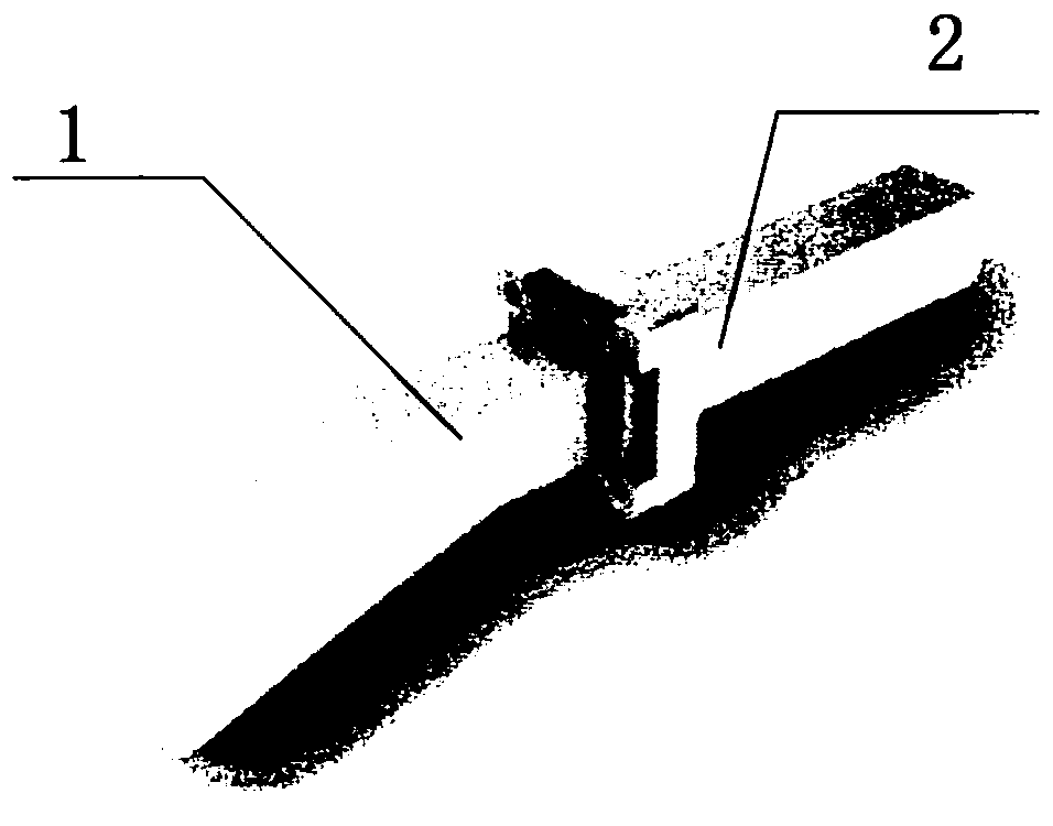
[0024] refer to Figure 1-6 As shown, an X-band low-grating-lobe circularly polarized antenna involved in this embodiment is used to provide grating-lobe suppression capabilities for large-spacing array antennas. It consists of a long horn antenna 1 and a diaphragm polarizer 2, wherein :

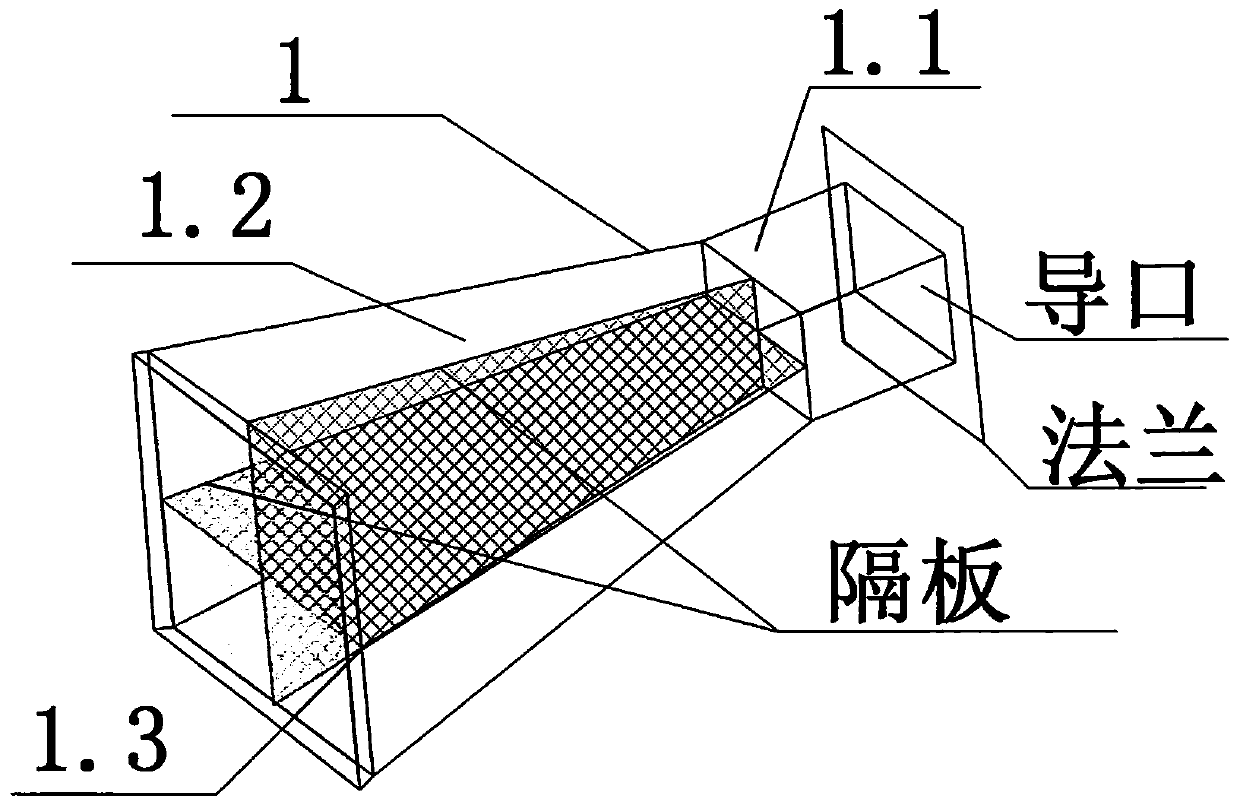
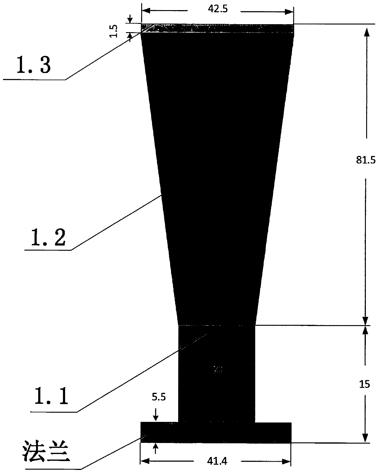
[0025] The long horn antenna 1 includes a feeding square waveguide 1.1, a horn waveguide 1.2, and a radiation surface 1.3. The long horn antenna 1 is evolved from a standard horn antenna. In order to increase the gain, the horn mouth has been extended. Optimizing the speaker; the feeding square waveguide 1.1 is a standard waveguide, which is used to realize the coupling and conversion of the diaphragm polarizer 2 sending and receiving signals. Feed, the signal received by the horn mouth is fed into the partition polarizer 2 here, and the feeding square wav...


PUM


Abstract

The invention relates to an X-band low-grating-lobe circularly polarized antenna, which is composed of a long horn antenna and a separator plate polarizer. The long horn antenna adopts a multi-inner-cavity design of metal separator plates. The aperture field distribution is improved by filling a radiation aperture surface with a dielectric material, so that the antenna gain and aperture efficiencyare improved, narrower directional diagram zero-point width is ensured, and grating lobe suppression capability is improved. The long horn antenna is connected with the separator plate polarizer through a flange in a waveguide cascade mode. The separator plate polarizer is a square waveguide with a metal separator plate in the middle, and the square waveguide is divided into two rectangular waveguides through the metal separator plate, so that a transmitting channel and a receiving channel are formed; and coaxial waveguide conversion of guide openings of the two rectangular waveguides is achieved through a stepped impedance converter. The X-band low-grating-lobe circularly polarized antenna adopts the waveguide as a main body structure, so that the complexity of structural design is simplified, the link loss is reduced, the utilization efficiency of the aperture of an array surface is improved, and the later-period assembly production and equipment debugging efficiency is improved.

Description

technical field [0001] The invention relates to an X-band low grating lobe circularly polarized antenna. It belongs to the technical field of antennas. Background technique [0002] The research and analysis on grating lobe suppression technology of large-spacing array antennas has developed very rapidly at home and abroad, and generally focuses on the array array method, which can adopt periodic or non-periodic arrangement. For the antenna array scheme with large element spacing, if the periodic arrangement is adopted, the array synthesis pattern will appear grating lobes in the real space, and as the scanning angle increases, the grating lobe level will increase accordingly, so the active subarray Aperiodic arrangement can be used, which can effectively reduce the grating lobe level. The active sub-array is composed of multiple antennas, and each antenna must have a high antenna gain, so that the array grating lobes can be effectively suppressed after combination. [00...

Claims


Application Information

Patent Timeline
Patent Type & Authority Applications(China)
IPC IPC(8): H01Q13/02H01Q1/36H01Q1/50H01Q15/24
CPCH01Q1/36H01Q1/50H01Q13/0241H01Q15/244
Inventor 刘四方凌元潘高峰张国歌张鹏谢勇李培周承斌胡湘江
Owner PLA NO 63686 CORPS
Why Eureka
Try Eureka