Support structure design method for complex part SLM forming

A technology of complex parts and support structures, which is applied in the field of support structure design and support structure design for SLM molding of complex parts, which can solve the problems of high processing cost, waste of manpower and material resources of SLM process.

Active Publication Date: 2020-01-10
CHENGDU ADVANCED METAL MATERIALS IND TECH RES INST CO LTD
View PDF16 Cites 16 Cited by
  • Summary
  • Abstract
  • Description
  • Claims
  • Application Information

AI Technical Summary

Problems solved by technology

In addition, the processing cost of SLM process is relatively high. If there is no scientific and effective processing system, it will inevitably cause unnecessary waste of manpower and material resources.

Method used


Image

  • Support structure design method for complex part SLM forming
  • Support structure design method for complex part SLM forming
  • Support structure design method for complex part SLM forming

Examples


specific Embodiment

[0035] The purpose of the present invention is to provide a more systematic design method for complex parts support, so that the quality of the printed parts is as high as possible, and the number of printing times is as few as possible, so as to reduce the processing cost.

[0036] The technical solution adopted to solve the above problems: to provide a support structure design method that satisfies the SLM forming of complex parts, including the following steps:

[0037] (1) Through the design pre-experiment, obtain the drape angle, hole, wall thickness, sharp corner, cylinder and other ultimate forming dimensions, support strength and removal difficulty involved in the printing under the forming process;

[0038] (2) Optimize the placement angle to avoid large overhangs during printing. For important processing surfaces, it should be placed on the top, and thin walls and round holes should be formed in the vertical direction;

[0039] (3) According to the structural characteristics ...

Embodiment 1

[0046] The content of the present invention will be described in detail in the following section with reference to the accompanying drawings.

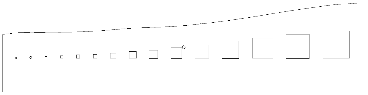
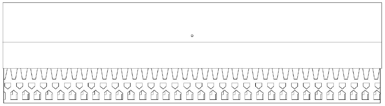
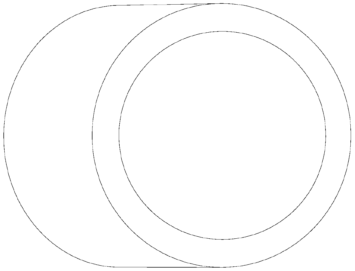
[0047] Through the pre-experiment, we must first understand the equipment's ability to process complex structural features such as overhanging planes, holes, wall thickness, sharp corners, and cylinders. Therefore, it is necessary to obtain the printed parts under the molding process in modeling software such as UG and Pro-E. Three-dimensional models of these structural features with different parameters involved, such as figure 1 As shown, the model is imported into Magics software in stl. format. Generally, the overhang angle can be set to 30~45°, the hole is The wall thickness is 0.1~1mm, the sharp angle is 5~30°, the cylinder is In addition, it is also necessary to set up a three-dimensional model for strength research under different support parameters (usually a long strip specimen with an aspect ratio greater than 3), such as fig...


PUM

PropertyMeasurementUnit
thicknessaaaaaaaaaa

Abstract

The invention discloses a support structure design method, in particular a support structure design method for complex part SLM forming, and belongs to the technical field of selective laser melting forming process design. By means of the support structure design method for complex part SLM forming, the normal progress of the machining process can be ensured, and the machining quality is effectively improved. The support structure design method includes the steps of obtaining complex part forming parameters, determining the forming part placement angle in the complex part forming process, arranging an easily-removed strong supporting structure, leading in a printing model, and conducting part printing and forming.

Description

Technical field [0001] The invention relates to a support structure design method, in particular to a support structure design method for SLM forming of complex parts, and belongs to the technical field of selective laser melting forming process design. Background technique [0002] 3D printing technology is a high-tech integration from three-dimensional digital model conceptual design to three-dimensional solid flexible manufacturing. It is based on the forming idea of ​​discrete / stacked additive manufacturing and comprehensively utilizes high-energy beam heat sources, computers, digital models, numerical control, and A high-tech advanced manufacturing technology that integrates multiple disciplines such as metallurgy and new materials. With the continuous promotion of the development of additive manufacturing technology, the application of this technology in various fields is also expanding. [0003] Since the Fraunhofer Laser Institute in Germany proposed the selective laser me...

Claims


Application Information

Patent Timeline
Patent Type & Authority Applications(China)
IPC IPC(8): B22F3/105B33Y10/00B33Y30/00B33Y50/00B33Y50/02
CPCB33Y10/00B33Y30/00B33Y50/00B33Y50/02B22F10/00B22F10/80B22F10/32B22F10/68B22F10/28B22F10/47B22F10/64Y02P10/25
Inventor 吴旺刘芯宇卢东刘永胜钟兵
Owner CHENGDU ADVANCED METAL MATERIALS IND TECH RES INST CO LTD
Why Eureka
Try Eureka