Hydrogen cell vacuum pipeline traffic vehicle

A technology of fuel cells and vacuum pipelines, applied in electric locomotives, railway vehicles, locomotives, etc., to achieve the effects of improving equipment utilization efficiency, reducing operating costs, and reducing pressure requirements

Active Publication Date: 2020-01-10
XIJING UNIV
View PDF15 Cites 3 Cited by
  • Summary
  • Abstract
  • Description
  • Claims
  • Application Information

AI Technical Summary

Problems solved by technology

However, the problem with this method is that a vehicle-mounted high-pressure air storage tank needs to be used, and the captured air in the pipeline is compressed by a compressor and stored in the air storage tank. After the vehicle

Method used


Image

  • Hydrogen cell vacuum pipeline traffic vehicle
  • Hydrogen cell vacuum pipeline traffic vehicle
  • Hydrogen cell vacuum pipeline traffic vehicle

Examples


Embodiment 1

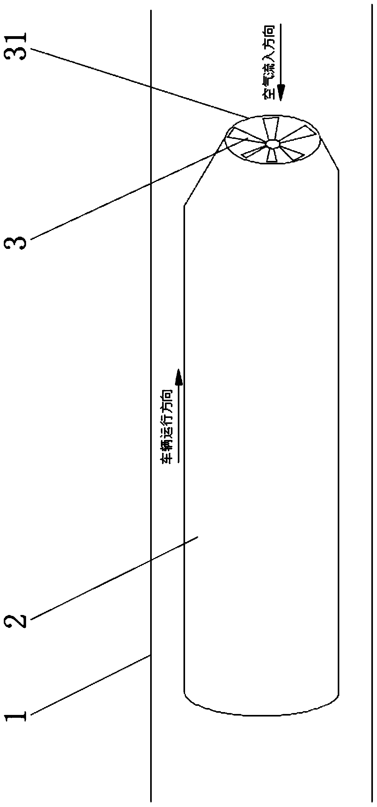
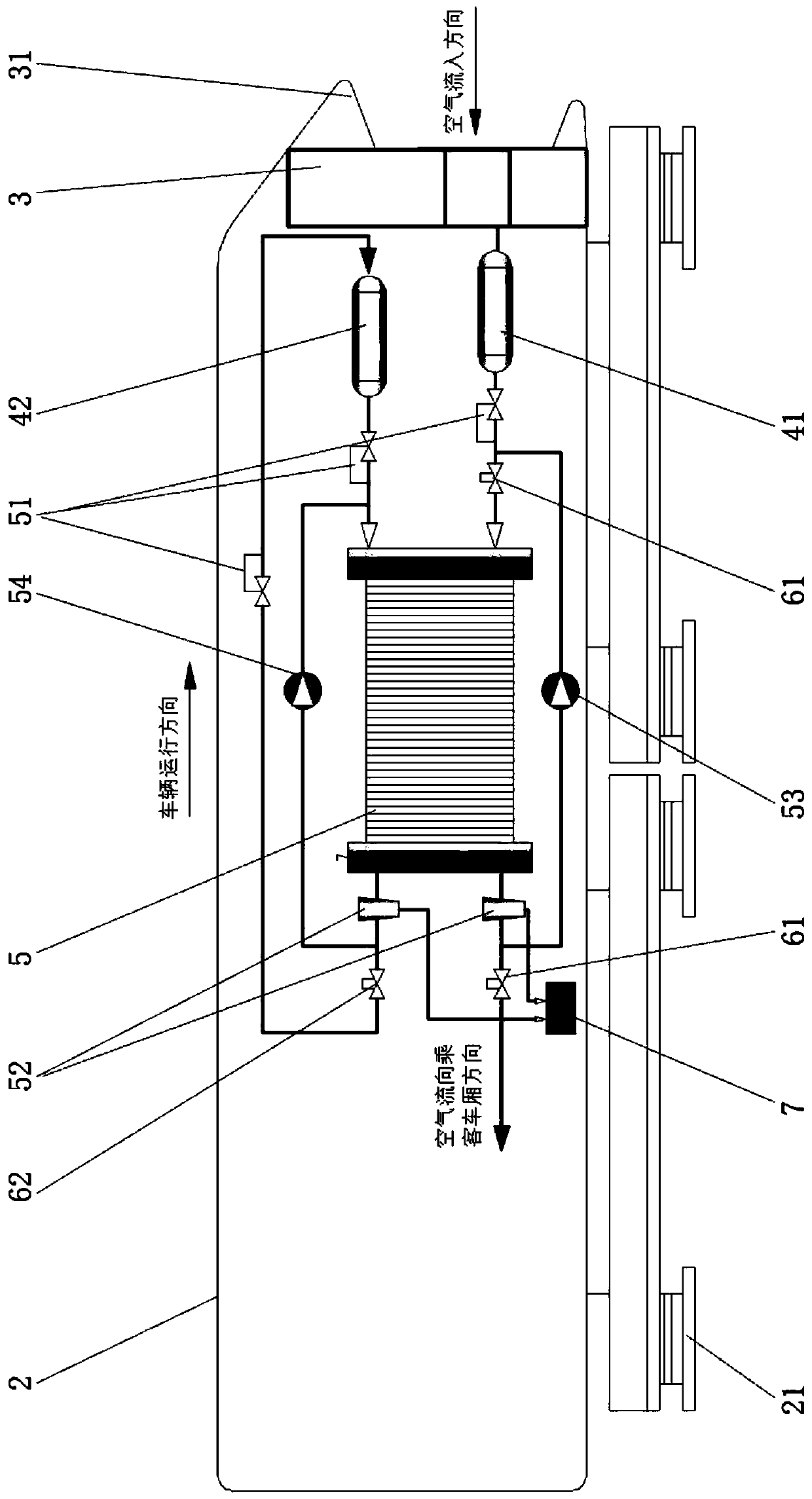
[0034] Example 1, such as figure 1 , figure 2As shown, a hydrogen fuel cell vacuum pipeline transportation vehicle includes a vacuum pipeline 1, a vehicle 2 is arranged in the vacuum pipeline 1, a vehicle suspension device 21 is provided on the outside of the vehicle 2, an air compressor 3 is provided at the front end of the vehicle 2, and an air compressor 3 is provided on the front end of the vehicle 2. The front end of compressor 3 is provided with air inlet 31, and the air outlet of air compressor 3 is connected with the air inlet of air bottle 41, and air bottle 41 is a kind of pressure vessel, and the air that catches is compressed into air by air compressor 3. Storage in the bottle 41; the air outlet of the air bottle 41 is connected with the air inlet of the air cleaner 61 through the pressure regulator 51, and the compressed air enters the air cleaner 61 after the air pressure is adjusted by the pressure regulator 51, and the air is in the air cleaner 61 After being...

Embodiment 2

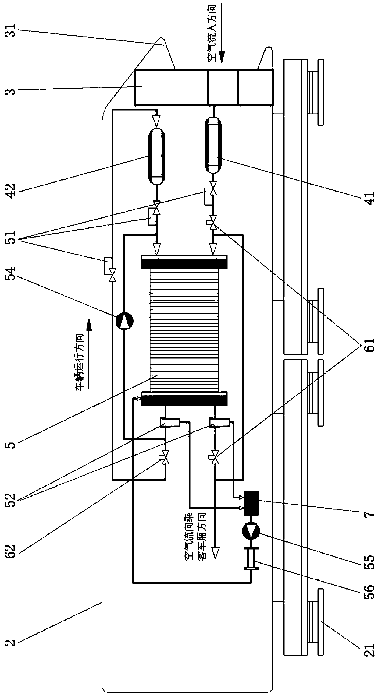
[0049] Example 2, such as figure 1 , image 3 As shown, a hydrogen fuel cell vacuum pipeline transportation vehicle, in addition to the structure of Embodiment 1, in order to humidify and heat the hydrogen-oxygen reaction process of the hydrogen fuel cell 5, the water tank 7 is passed through a water pump 55 and a heat exchanger 56 Connection, heat exchanger 56 gas outlet is connected with hydrogen fuel cell 5, heat exchanger 56 has humidification function, is a kind of humidifier in essence, heat exchanger 56 utilizes the heat that hydrogen and oxygen reaction process produces to heat, from water tank 7 The outflowing water is heated in the heat exchanger 56 to form water vapor and flows into the hydrogen fuel cell 5 cell stack through pipelines to humidify and heat the hydrogen fuel cell 5 to improve the reaction efficiency.

[0050] In this embodiment, a method for operating a hydrogen fuel cell vacuum pipeline transportation vehicle includes the following steps:

[0051]...


PUM


Abstract

The invention discloses a hydrogen cell vacuum pipeline traffic vehicle. A vehicle suspension device is arranged on the outer side of a vehicle, an air compressor is arranged at the front end of the vehicle, the air compressor is connected with an air bottle, the air bottle is connected with the inlet of an air purifier through a pressure regulator, after air is purified in the air purifier, one part of the air enters a passenger compartment of the vehicle through a pipeline for the breathing use of passengers in the vehicle, and the other part of the air enters a hydrogen cell through the airinlet of the hydrogen cell by an injector, the hydrogen inlet of the hydrogen cell is connected with the air outlet of the air bottle, a water-gas mixture from the water outlet of the hydrogen cell is separated by a separator, separated water enters a water tank through the pipeline, separated air enters the air inlet of the hydrogen cell again through an air circulation pump, and separated hydrogen enters the hydrogen inlet of the hydrogen cell again through a hydrogen circulation pump. According to the hydrogen cell vacuum pipeline traffic vehicle, clean energy is advantageously promoted, the utilization efficiency of equipment is improved, and the operation cost is lowered.

Description

technical field [0001] The invention belongs to the technical field of vacuum pipeline transportation, and in particular relates to a hydrogen fuel cell vacuum pipeline transportation vehicle. Background technique [0002] Vacuum pipeline transportation is to build an airtight pipeline on the ground or underground, lay a magnetic levitation track in the pipeline, and pump it into a certain vacuum, and the magnetic levitation vehicle travels in it. Due to the elimination of air resistance and mechanical friction at the same time, the speed of the vacuum tube maglev vehicle can reach supersonic speed, even hypersonic speed. For submarine vacuum pipelines designed to cross the strait, steel rails can be laid in the pipeline, and a certain vacuum can be evacuated, and wheel-rail vehicles can run in it. Due to the elimination of air resistance, the wheel-rail high-speed train can travel across the strait at high speed. [0003] The pipe diameter of vacuum pipeline transportatio...

Claims


Application Information

Patent Timeline
IPC IPC(8): B61B13/10B61B13/08B61C3/00
CPCB61B13/08B61B13/10B61C3/00
Inventor 张耀平林东张蕴潘建民刘子忠刘甲鹏张志宇刘本林李胜善
Owner XIJING UNIV
Why Eureka
Try Eureka