Environment-friendly energy-saving furnace

An environmental protection and energy-saving furnace body technology, which is applied to household furnaces/stoves, furnaces/stoves with hot water devices, heating methods, etc., can solve insufficient coal combustion, reduce heat conversion efficiency, and affect environmental quality, etc. problems, to achieve the effect of ensuring the efficiency and quality of heat transfer, improving the quality of preheating, and increasing the contact area

Active Publication Date: 2020-01-10
汪玉慧
View PDF5 Cites 1 Cited by
  • Summary
  • Abstract
  • Description
  • Claims
  • Application Information

AI Technical Summary

Problems solved by technology

[0004] In order to better reduce the energy consumption of the existing coal-fired heating furnace, a preheating pipe will be installed in the exhaust pipe, so that the heat of the flue gas can be well absorbed, but the existing direct-fired coal furnace does not burn coal. Sufficiently, there is a lot of waste slag discharge, which will not only affect the environmental quality, but after a long time, the waste slag will be attached to the pipeline to form a thick layer, which will reduce the efficiency of heat conversion and affect the quality of preheating, and when cleaning the furnace ash, A large amount of furnace dust will float in the air, which is not conducive to protecting the environment. Therefore, we have proposed an environmentally friendly and energy-saving furnace to solve the above problems

Method used


Image

  • Environment-friendly energy-saving furnace
  • Environment-friendly energy-saving furnace
  • Environment-friendly energy-saving furnace

Examples


Embodiment Construction

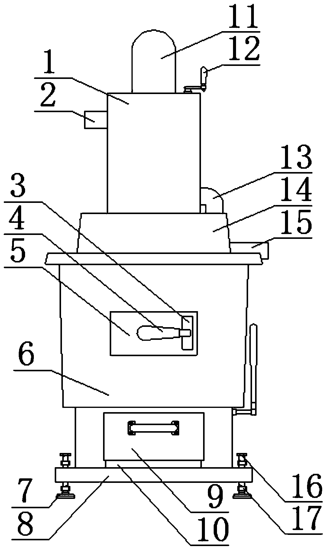
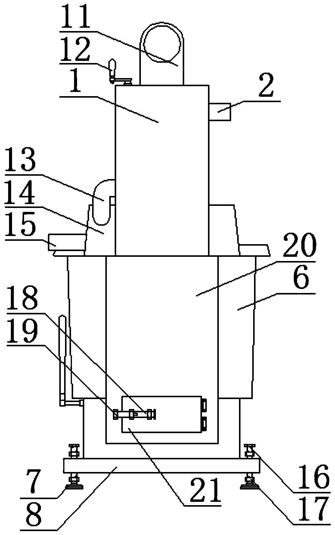
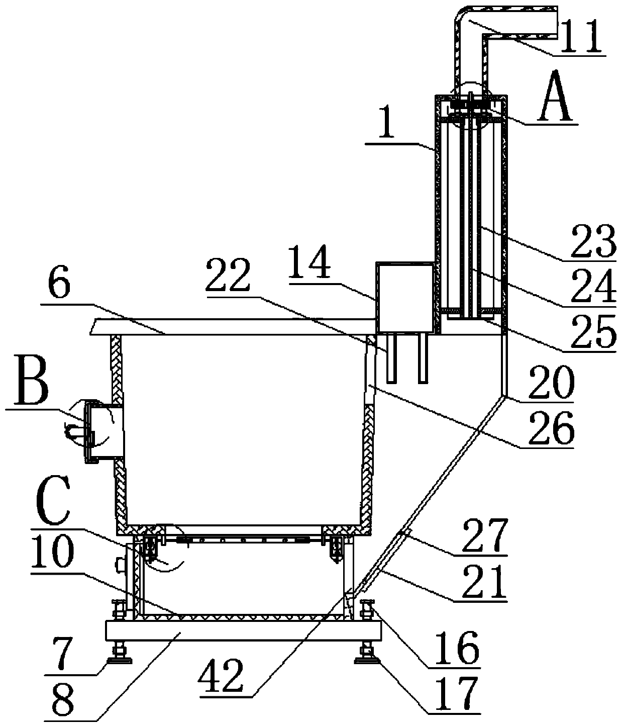
[0038] The following will clearly and completely describe the technical solutions in the embodiments of the present invention with reference to the accompanying drawings in the embodiments of the present invention. Obviously, the described embodiments are only some, not all, embodiments of the present invention.

[0039] refer to Figure 1-12 , an environmentally friendly and energy-saving furnace, including a furnace body 6, the lower end of the furnace body 6 is provided with a support mechanism, which can well adapt to the ground in different situations, ensures the stability of the furnace body 6, and avoids the instability of the furnace body 6 due to uneven ground Situation takes place, avoid body of heater 6 toppling over, and support mechanism comprises the base plate 8 that is fixed on the lower end of body of heater 6, and base plate 8 is fixed on the lower end of body of heater 6 by welding, promotes the solid degree of connection.

[0040] In the present invention,...


PUM


Abstract

The invention discloses an environment-friendly energy-saving furnace. A furnace body is included. A supporting mechanism is arranged at the lower end of the furnace body. The side wall of one inner end of the furnace body is sequentially provided with a first opening and a fourth opening from top to bottom. A shell is fixed to one side of the furnace body. An opening and closing mechanism is arranged on one side of the lower end of the shell. The contact area is increased by increasing the number of second sleeves, the quality of heat transfer is guaranteed by rapidly clearing waste slag on the inner walls of the second sleeves, accordingly, the heat conversion efficiency can be effectively improved, the water preheating efficiency is improved, and the energy utilization rate is increased. A support rod can be used for screening out coal slag so that the coal combustion quality can be guaranteed, a water spraying pipe is used for humidifying the screened-out coal slag and the fallingwaste slag, flying dust generated when furnace slag in a bearing frame is cleared is avoided, accordingly, the quality of the surrounding environment during furnace ash clearing can be better protected, and the functions of energy saving and environment protection are achieved. The advantages that the situation in the furnace body is conveniently observed, and furnace body stability is guaranteedare achieved.

Description

technical field [0001] The invention relates to the technical field of energy-saving furnaces, in particular to an environment-friendly and energy-saving furnace. Background technique [0002] Coal-fired heating stoves are economical and affordable. Coal-fired heating stoves with lower heating costs are ideal for urban-rural fringe areas and vast rural areas without central heating and gas heating regulation. [0003] Existing coal-fired heating furnaces generally include a furnace body and a water pipe located on the top side of the furnace body in terms of structure. The coal is directly burned to heat the water pipe, and the heated water is pumped to the heating part of the building, where it is replaced at the radiator. Heat, thereby increasing the temperature in the house, and can make the water cycle, reducing the waste of water resources. [0004] In order to better reduce the energy consumption of the existing coal-fired heating furnace, a preheating pipe will be in...

Claims


Application Information

Patent Timeline
IPC IPC(8): F24B1/183F24B1/189F24B1/191F24B13/00F23J1/00
CPCF23J1/00F24B1/183F24B1/189F24B1/191F24B1/1915F24B13/006
Inventor 不公告发明人
Owner 汪玉慧
Why Eureka
Try Eureka