Multi-station conveying facility

A transmission equipment and multi-station technology, applied in the direction of conveyors, conveyor objects, rollers, etc., can solve problems such as many fault points, high equipment manufacturing costs, complex electronic control and mechanical systems, etc.

Pending Publication Date: 2020-01-14
CITIC DICASTAL
View PDF0 Cites 1 Cited by
  • Summary
  • Abstract
  • Description
  • Claims
  • Application Information

AI Technical Summary

Problems solved by technology

Specifically, the present invention intends to provide a reciprocating belt-type pneumatic synchronous transmission mechanism, which solves the problems of high equipment manufacturing cost, high equipment energy consumption, relatively complicated electronic control and mechanical systems, many fault points, The beat of the feed mode is too slow, etc.

Method used


Image

  • Multi-station conveying facility
  • Multi-station conveying facility
  • Multi-station conveying facility

Examples


Embodiment 1

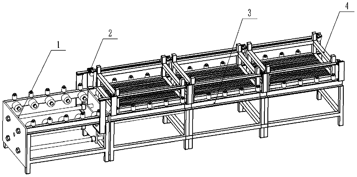
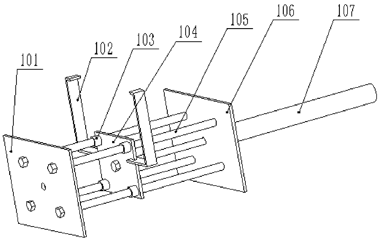
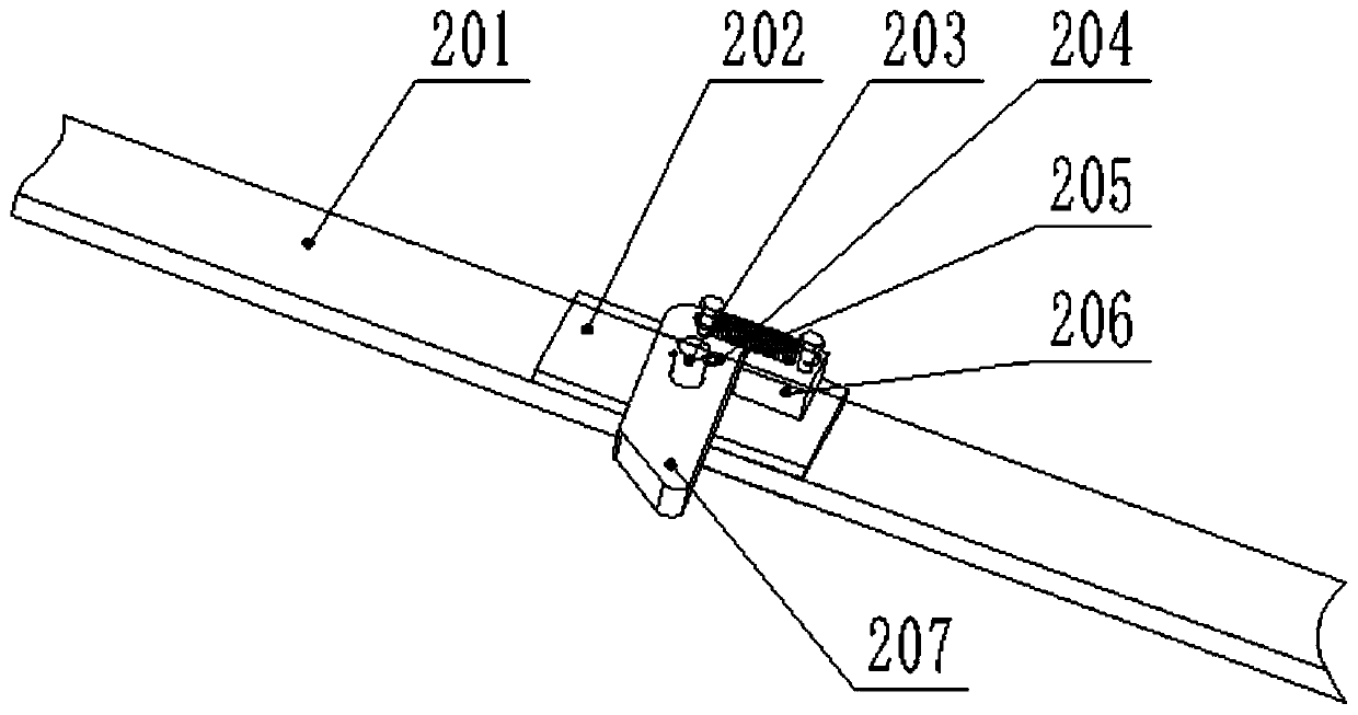
[0034] Embodiment 1 of the present invention will be specifically described below in conjunction with the accompanying drawings: a reciprocating pull belt type pneumatic synchronous transmission mechanism, including a cylinder drive mechanism, a pull belt shifting fork mechanism, and a transmission station mechanism, wherein the cylinder drive mechanism includes a front fixing plate, a connecting Arm, guide sleeve, movable plate, guide rod, rear fixed plate, cylinder; pull belt fork mechanism includes pull belt, bottom plate, pin shaft, cotter pin, spring, stopper, fork; transmission station mechanism includes bracket, slot Steel, support roller bracket, support roller, guide wheel, bottom transfer wheel.

[0035] In the cylinder drive mechanism, the two ends of the four guide rods are respectively fixed on the front fixed plate and the rear fixed plate through screw connections, and a guide sleeve is installed on each guide rod, and the four guide sleeves are fixed on the mova...


PUM


Abstract

The invention relates to a multi-station conveying facility. The multi-station conveying facility comprises a driving device, a transmission engaging device and a station combination device. The station combination device comprises multiple conveying station mechanisms (3) which are arranged in sequence in the mode of corresponding to multiple stations. A material frame (4) is suitable for being placed and supported on each conveying station mechanism. The driving device can drive the multiple material frames on the multiple conveying station mechanisms to synchronously move through the transmission engaging device. The transmission engaging device comprises at least one pulling belt and shifting fork mechanism (2). The pulling belt and shifting fork mechanisms are driven by the driving device to conduct reciprocating movement, and the material frames are driven to simultaneously advance. An electrical system and a mechanical system in an existing conveying mechanism are simplified, the manufacturing cost of the facility and the energy consumption of the facility are reduced, the number of fault points is reduced, and the working efficiency is improved by the simultaneous and synchronous conveying operation.

Description

technical field [0001] The invention relates to a multi-station transmission device, in particular applied to the technical field of fluorescence detection equipment. Background technique [0002] In the casting production process of aluminum alloy parts, the castings after heat treatment need to be tested for surface cracks, and fluorescence testing equipment is generally used for non-destructive testing on the surface of castings. During fluorescence detection, the casting is placed in a standard material frame, and it passes through several stations such as impregnation (soak the casting in the fluorescent liquid), dripping, soaking, spraying, drying, etc. and stays in each station for an equal time, and finally Enter the dark room, and the operator uses purple light to detect the surface of the workpiece one by one. The transmission of the material frame between each station requires a drive mechanism. The existing drive mechanism consists of a drive motor and a sprocke...

Claims


Application Information

Patent Timeline
Patent Type & Authority Applications(China)
IPC IPC(8): B65G25/06B65G25/08B65G13/04B65G39/18
CPCB65G13/04B65G25/06B65G25/08B65G39/18B65G2201/02B65G25/10B65G2201/0258B65G13/00B65G41/006B65G2812/12
Inventor 李耐力白亚江熊彬羽
Owner CITIC DICASTAL
Why Eureka
Try Eureka