
Dry hanging drill bit

A drill and dry-hanging technology, applied in stone processing tools, work accessories, manufacturing tools, etc., can solve the problems of affecting the aesthetics and stability of plates, uneven fixing of multiple plates, poor accuracy and stability, etc. Drilling Efficiency and Drilling Quality, Reduced Drilling Quality Degradation, Effect of Controlling Drilling Depth

Inactive Publication Date: 2020-01-17
GUANGZHOU CRYSTAL TECH
View PDF0 Cites 0 Cited by
  • Summary
  • Abstract
  • Description
  • Claims
  • Application Information

AI Technical Summary

Problems solved by technology

[0003] The cutting head in the dry-hanging drill bit used in the above-mentioned drilling equipment is not concentric with the drill rod, so that when drilling, a blind hole with a large inside and a small outside will be formed. The cutting head in the traditional dry-hanging drill is almost all In the flat plate structure, the upper and lower ends of the cutting head are in contact with the plate during the drilling process, making it difficult to discharge slag. The accumulation of waste slag in the blind hole will participate in the grinding of the grinding surface, resulting in low drilling efficiency, Poor drilling quality, which affects the aesthetics and stability of the panel fixing
In addition, because the thickness of the plate may have a certain deviation, the depth of the drilling must be flexibly adjusted according to the actual thickness of the plate when drilling, otherwise it will cause unevenness when fixing multiple plates. The problem is that at present, the drilling depth can only be controlled by the proficiency of the workers, and the accuracy and stability are poor.

Method used


Image

  • Dry hanging drill bit
  • Dry hanging drill bit
  • Dry hanging drill bit

Examples


Embodiment 1

[0018] This embodiment proposes a dry-hanging drill bit that is easy to discharge slag and drain and control the drilling depth, so as to improve drilling efficiency and drilling quality.

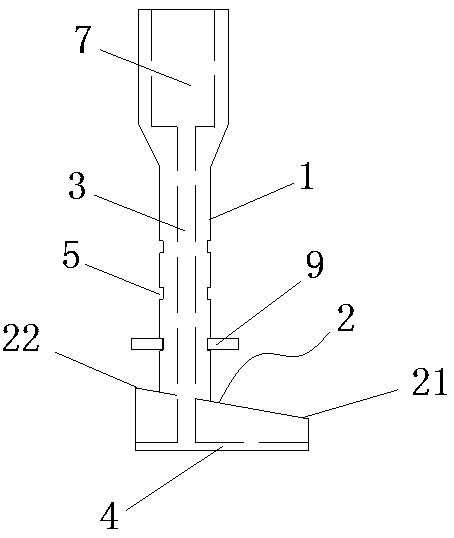
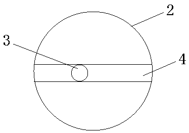
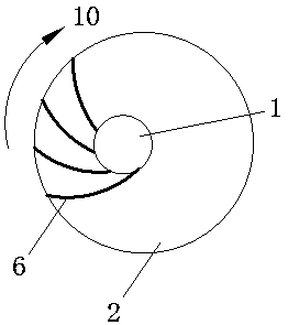
[0019] Such as figure 1 , 2 As shown, the dry-hanging drill bit of this embodiment is composed of a drill rod 1 and a cutting head 2 welded to the bottom end of the drill rod 1 in an eccentric state. The top of the hole 3 is connected to the threaded assembly hole 7 of the drill pipe 1; the bottom surface of the cutting head 2 is provided with a water guide groove 4 communicating with the water guide hole 3, and the two ends of the water guide groove 4 extend to the head end 21 of the cutting head 2 respectively. and the tail end 22; the bottom surface of the cutting head 2 is a plane, the cutting head 2 is circular, and its head end 21 is farther away from the drill pipe 1 than the tail end 22, and the thickness of the cutting head 2 gradually increases from the head end 21 to the tail en...


PUM


Abstract

The invention provides a dry hanging drill bit. Slagging and drainage are easy, the drilling depth is easy to control, and the drilling quality is improved. The dry hanging drill bit is composed of adrill rod and a cutting head eccentrically arranged at the bottom end of the drill rod. The drill rod and the cutting head are provided with communicating water guide holes, and a water guide groove communicating with the water guide holes is formed in the bottom face of the cutting head. The dry hanging drill bit is characterized in that he bottom face of the cutting head is a plane, the head endof the cutting head is more away from the drill rod compared with the tail end, and the thickness of the cutting head is gradually increased from the head end to the tail end; and a plurality of clamping spring grooves are formed in the drill rod at intervals. Due to the fact that the thickness of the cutting head gradually changes, the top face of a blind hole cannot be in contact with the top face of the head end in the drilling process, and a clearance formed in this position is beneficial for cooling water and waste slag to flow out of the blind hole. Aiming at different drilling depth requirements, clamping springs can be mounted in the proper clamping spring grooves; and when the surface of a plate is in contact with the clamping springs, it shows that the drilling depth meets the requirements, and the drilling depth can be accurately controlled more easily.

Description

technical field [0001] The invention belongs to the technical field of electric tools, and in particular relates to a drill bit. Background technique [0002] The stone dry hanging method, also known as the empty hanging method, is a new construction technology in the current wall decoration. This method uses metal pendants to directly hang the facing stone on the wall or hang it on the steel frame without grouting and pasting. The principle is to set the main stress points on the main structure, and fix the stone on the building through metal pendants to form a stone decorative curtain wall. At present, the common method of fixing plates is the back-bolt type. The specific method is to use professional drilling equipment to precisely process round holes with large inside and small outside on the back of the porcelain plate, insert the anchor bolts into the holes, and screw them into the screws. , so that the bottom of the anchor bolt is fully expanded, and matches the tap...

Claims


Application Information

Patent Timeline
Patent Type & Authority Applications(China)
IPC IPC(8): B28D1/14B28D7/02
CPCB28D1/14B28D7/02
Inventor 魏洪涛吴益雄陈炜彭明毛华斌
Owner GUANGZHOU CRYSTAL TECH
Learn More