Power transmission device
A technology of power transmission device and driving force, applied in the direction of magnetic drive clutch, non-mechanical drive clutch, clutch, etc., can solve the problem of insufficient sound suppression.
- Summary
- Abstract
- Description
- Claims
- Application Information
AI Technical Summary
Problems solved by technology
Method used
Image

Examples
no. 1 approach
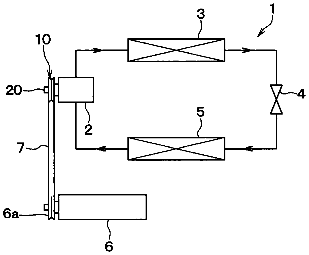
[0037] The refrigeration cycle 1 functions as a device for adjusting the temperature of air blown into the vehicle interior in a vehicle air conditioner for air-conditioning the vehicle interior. The refrigeration cycle 1 is composed of a closed circuit, which is formed by connecting the compressor 2, the radiator 3, the expansion valve 4 and the evaporator 5 in a ring shape. The compressor 2 compresses and discharges the refrigerant, and the radiator 3 makes the The refrigerant discharged from the compressor 2 dissipates heat, the expansion valve 4 decompresses the refrigerant flowing out of the radiator 3 , and the evaporator 5 evaporates the refrigerant decompressed by the expansion valve 4 .
[0038] The rotational driving force output from the engine 6 is transmitted to the compressor 2 via the power transmission device 10 . In the present embodiment, the engine 6 constitutes a drive source that outputs a rotational drive force, and the compressor 2 constitutes a drive ta...
no. 2 approach
[0108] use Figure 14-Figure 15 A second embodiment will be described. Such as Figure 14 As shown, in the power transmission device of the present embodiment, a protrusion 183 c is formed on one surface side of the vibration damper 183 of the rubber member 18 . Such as Figure 15 As shown, the protrusion 183 c is inserted into the groove 141 formed in the armature 14 .
[0109] One surface of the protrusion 183 c is in contact with both the outer plate 142 on the outer peripheral side of the groove 141 and the inner plate 143 on the inner peripheral side of the groove 141 , and the other surface of the protrusion 183 c is in contact with the outer connecting portion 161 .
[0110] As described above, vibration damper 183 has protrusion 183 c protruding toward one side, and protrusion 183 c is inserted into groove 141 formed in armature 14 . Therefore, it is possible to reduce the operation noise when the outer panel 142 is connected to the outer hub 16 by fastening member...
no. 3 approach
[0112] use Figure 16 A third embodiment will be described. The damper portion 183 of the rubber member 18 of the present embodiment has a first region 1831 having a first thickness and a second region 1832 having a second thickness thicker than the first thickness. In addition, unevenness is formed on the surfaces of the first region 1831 and the second region 1832 that face the armature 14 .
[0113] In this way, the damper 183 can have a first region 1831 having a first thickness and a second region 1832 having a second thickness thicker than the first thickness.
PUM
| Property | Measurement | Unit |
|---|---|---|
| Melting point | aaaaa | aaaaa |
Abstract
Description
Claims
Application Information
 - R&D
- Intellectual Property
- Life Sciences
- Materials
- Tech Scout
- Unparalleled Data Quality
- Higher Quality Content
- 60% Fewer Hallucinations
Browse by: Latest US Patents, China's latest patents, Technical Efficacy Thesaurus, Application Domain, Technology Topic, Popular Technical Reports.
© 2025 PatSnap. All rights reserved.Legal|Privacy policy|Modern Slavery Act Transparency Statement|Sitemap|About US| Contact US: help@patsnap.com