Recyclable shot blasting device

A technology of shot blasting and equipment, which is applied in the direction of metal processing equipment, used abrasive processing devices, abrasive jetting machine tools, etc., can solve problems affecting the service life of the device, fracture or damage, and affect the safe use of the rotating cylinder, etc., to improve Lifespan, effect of preventing breakage or shattering

Active Publication Date: 2020-01-21
南京六合高新建设发展有限公司
View PDF11 Cites 2 Cited by
  • Summary
  • Abstract
  • Description
  • Claims
  • Application Information

AI Technical Summary

Problems solved by technology

[0005] In order to make up for the deficiencies of the prior art, the invention proposes a recyclable shot peening equipment. The invention is mainly used to solve the problem that the projectiles are piled up in the device during the existing shot peening operation, the number of required projectiles increases sharply, and the number of projectiles is greatly increased. Failure to recycle in time will cause the device to engage and affect the service life of the device. At the same time, during shot peening, the high-speed particle projectiles sprayed will damage the fixedly installed rotating cylinder in the body. When the rotating cylinder is used in the body for a long time, it is easy to cause Breakage or breakage, which will affect the safe use of the rotating drum

Method used


Image

  • Recyclable shot blasting device
  • Recyclable shot blasting device
  • Recyclable shot blasting device

Examples


specific Embodiment approach

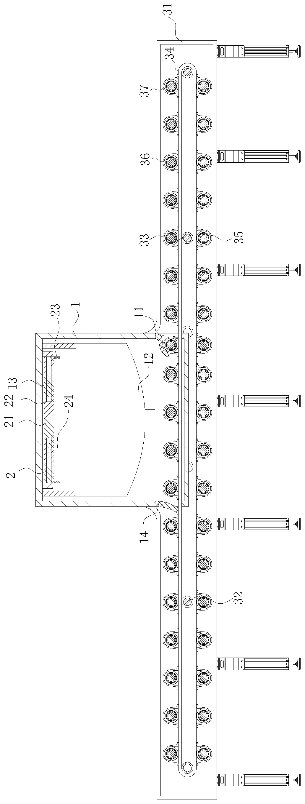
[0029] As a specific embodiment of the present invention, the conversion mechanism 5 includes a driving motor 51, a mounting plate 52, a guiding telescopic rod 53, a rotating guide sleeve 54, a driving gear 56 and a driven gear 57; The plate 52 is installed on the outer wall of the installation frame 31, and the output end of the drive motor 51 is connected with a guide telescopic rod 53; The end passes through the installation frame 31 and is connected with a driving gear 56; the driven gear 57 is installed on the ends of the first rotating shaft 32 and the second rotating shaft 35 respectively; the driving gear 56 is connected to the first rotating shaft 32 and the second rotating shaft The driven gear 57 installed on the two rotating shafts 35 is slidingly engaged, and the driving gear 56 and the driven gear 57 are all set to spur gears; The controller will control the electric telescopic rod to stretch out, and the stretched electric telescopic rod will drive the driving g...

Embodiment approach

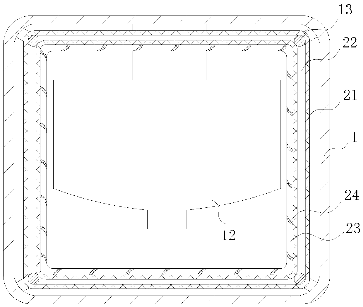
[0032] As a specific embodiment of the present invention, a rubber ring 9 is fixedly installed on the second rotating shaft 35, and a magnet ring 10 is installed on the outer wall of the rubber ring 9, and the circumference of the magnet ring 10 is 9 times that of the rubber ring 9. half; the outer wall of the rotating cylinder 4 is provided with a swing cavity 47, and a metal burr sheet 11 is slidably installed in the swing cavity 47; the bottom end of the metal burr sheet 11 is provided with a magnet block, and the magnet block and the magnet ring are The same magnetic pole; during work, when the second rotating shaft 35 rotates, the second rotating shaft 35 will drive the rubber ring 9 to rotate, and the rubber ring 9 will drive the magnet ring 10 to rotate in the rotating cylinder 4, because the outer wall of the rotating cylinder 4 slides A metal burr sheet 11 is provided, and the repulsive force of the rotation of the magnet ring will cause the metal burr sheet 11 to prot...


PUM


Abstract

The invention belongs to the technical field of industrial production, and particularly discloses a recyclable shot blasting device. An installing frame is installed on the two sides of an opening ofa machine body in a penetrating mode. A rotating frame is formed in the inner side of the installing frame. A plurality of first rotating shafts are installed in the installing frame through a rotating sleeve in the horizontal direction of the installing frame. The first rotating shafts are sleeved with rotating rollers. Rotating bearings are arranged at the two ends of each second rotating shaftcorrespondingly. The rotating bearings are installed on a conveying belt through fixing sleeves. Rotating belt wheels are installed at the two ends of each second rotating shaft. The rotating belt wheels are located outside the rotating bearings. The rotating belt wheels are rotationally connected through a belt. A rotating cylinder is installed on each second rotating shaft. A converting mechanism is arranged outside the installing frame and used for exerting the transmission effect on the conveying belt and the rotating cylinders. It is effectively avoided that the fracture or breakage phenomenon is generated when the rotating cylinders work for a long time in the machine body and the safety operation of the rotating cylinders is affected.

Description

technical field [0001] The invention belongs to the technical field of industrial production, in particular to a recyclable shot blasting equipment. Background technique [0002] Castings need to be shaken out, cored and cleaned after they are manufactured. Manual cleaning is not only inefficient, but also often fails to meet the requirements, which directly affects the overall quality of castings. Therefore, more and more factories use Shot blasting machine to replace traditional manual cleaning. [0003] Shot blasting machine is a casting equipment that uses high-speed projectiles ejected from a shot blasting device to clean or strengthen the surface of castings. The shot blasting machine hits the surface of the metal with one or more sand materials to eliminate some attachments on the metal surface, such as rust. Or obtain a specific surface layer by shot blasting impact. [0004] While existing shot blasting machines are in use, most of the conveying devices of shot bl...

Claims


Application Information

Patent Timeline
Patent Type & Authority Applications(China)
IPC IPC(8): B24C3/12B24C9/00B65G13/02B65G13/06B65G39/04
CPCB24C3/12B24C9/003B24C9/006B65G13/02B65G13/06B65G39/04B65G2811/09
Inventor 王俊华王中刚张翔
Owner 南京六合高新建设发展有限公司
Why Eureka
Try Eureka