
Array substrate manufacturing method and array substrate

A manufacturing method and array substrate technology, applied in semiconductor/solid-state device manufacturing, optics, instruments, etc., can solve the problems of complex process and high production cost, and achieve the effects of saving photolithography process, protecting balance ability, and reducing process difficulty

Inactive Publication Date: 2020-01-21
CHENGDU ZHONGDIAN PANDA DISPLAY TECH CO LTD
View PDF5 Cites 5 Cited by
  • Summary
  • Abstract
  • Description
  • Claims
  • Application Information

AI Technical Summary

Problems solved by technology

[0004] The six photolithography process provided by the above-mentioned prior art is complex in process and high in production cost

Method used


Image

  • Array substrate manufacturing method and array substrate
  • Array substrate manufacturing method and array substrate
  • Array substrate manufacturing method and array substrate

Examples


Embodiment 1

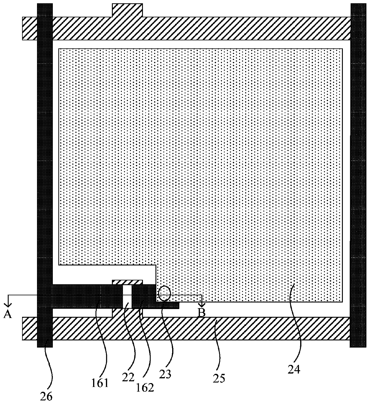
[0068] figure 1 For the plan view of the array substrate provided by the embodiment of the present invention, refer to figure 1 As shown, the array substrate provided by the embodiment of the present invention includes a source electrode 161, a drain electrode 162, a passivation layer 22, a conductive via hole 23, a pixel electrode 24, a scanning line 25 and a data line 26, wherein the pixel electrode 24 is connected through a conductive via The hole 23 communicates with the drain 162, the scan line 25 communicates with the gate 12 and both are formed in the same photolithography process, the data line 26 communicates with the source 161 and both are formed in the same photolithography process, it should be noted that , figure 1 is the plan view of the array substrate, due to the viewing angle, some structures of the array substrate are not in the figure 1 , so it is not presented here.

[0069] figure 2 The flow chart of the manufacturing method of the array substrate pr...

Embodiment 2

[0089] An embodiment of the present invention provides an array substrate, which is fabricated by the method described in Embodiment 1, such as figure 1 and Figure 9 As shown, the array substrate includes: a base substrate 11 and a gate 12, a gate insulating layer 13, a first semiconductor layer 141, a second semiconductor layer 142, a first barrier layer 151, The second barrier layer 152, the source-drain metal layer, the passivation layer 22 and the pixel electrode 24, the source-drain metal layer includes a source electrode 161 and a drain electrode 162, and a channel region 21 is provided between the source electrode 161 and the drain electrode 162; wherein, The first semiconductor layer 141 is a metal oxide semiconductor with low oxygen content, and the second semiconductor layer 142 is a metal oxide semiconductor with high oxygen content; the passivation layer 22 has a conductive via hole 23, and the pixel electrode 24 passes through the conductive via hole 23 and The ...


PUM


Abstract

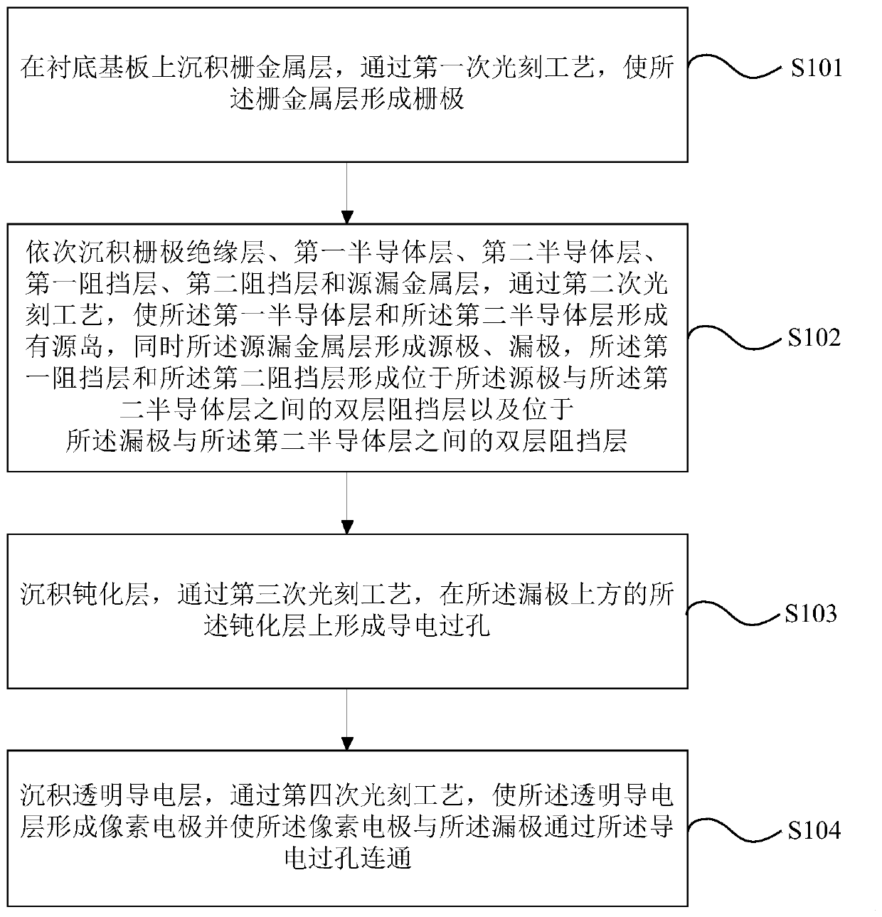
The invention provides an array substrate manufacturing method and an array substrate, and the array substrate manufacturing method comprises the steps: depositing a gate metal layer on a substrate, and enabling the gate metal layer to form a gate electrode through a first photoetching process; sequentially depositing a gate insulating layer, a first semiconductor layer, a second semiconductor layer, a first barrier layer, a second barrier layer and a source-drain metal layer, forming an active island by the first semiconductor layer and the second semiconductor layer through a second photoetching process, and forming a source electrode and a drain electrode by the source-drain metal layer; depositing a passivation layer, and forming a conductive via hole in the passivation layer above thedrain electrode through a third photoetching process; and depositing a transparent conductive layer, enabling the transparent conductive layer to form a pixel electrode through a fourth photoetchingprocess, and enabling the pixel electrode to be communicated with the drain electrode through a conductive via hole. According to the manufacturing method and the array substrate provided by the invention, the manufacturing of the array substrate can be realized only by the four photoetching processes, the process is simple, and the manufacturing cost is low.

Description

technical field [0001] The invention relates to the technical field of liquid crystal display, in particular to a method for manufacturing an array substrate and the array substrate. Background technique [0002] With the development of display technology, flat display devices such as liquid crystal displays (LCD) are widely used in mobile phones, televisions, personal In various consumer electronic products such as digital assistants and notebook computers, it has become the mainstream of display devices. A liquid crystal display panel generally consists of an array substrate, a color filter substrate, and a layer of liquid crystal molecules sandwiched between the array substrate and the color filter substrate. By applying a driving voltage between the array substrate and the color filter substrate, the liquid crystal molecules can be controlled to rotate, so that the light from the backlight module is refracted to produce a picture. [0003] The manufacturing method of t...

Claims


Application Information

Patent Timeline
Patent Type & Authority Applications(China)
IPC IPC(8): H01L27/12H01L29/786H01L21/77G02F1/1362G02F1/1368
CPCG02F1/136277G02F1/1368H01L27/1225H01L27/1288H01L29/78606H01L29/78693
Inventor 刘翔孙学军李广圣马群
Owner CHENGDU ZHONGDIAN PANDA DISPLAY TECH CO LTD
Learn More