Ultrasonic cavitation shot peening method and its application device

An ultrasonic and shot peening technology, which is applied in the field of ultrasonic cavitation shot peening method and its use device, can solve the problems of limited application and inability to apply to metal surfaces with complex shapes, and achieve the effects of high processing efficiency, overcoming attenuation phenomenon, and easy operation

Active Publication Date: 2021-06-22
NINGBO INST OF MATERIALS TECH & ENG CHINESE ACADEMY OF SCI
View PDF6 Cites 0 Cited by
  • Summary
  • Abstract
  • Description
  • Claims
  • Application Information

AI Technical Summary

Problems solved by technology

Due to the attenuation of ultrasonic cavitation intensity in the liquid medium and the limitation of the output power of the ultrasonic system, the main form of ultrasonic cavitation shot peening is near-field ultrasonic cavitation shot peening. The surface distance of the shot workpiece is very close, only about 1mm, and ultrasonic cavitation shot peening can only be carried out for simple and flat metal surfaces, which cannot be applied to metal surfaces with complex shapes, which seriously limits its application in engineering

Method used


Image

  • Ultrasonic cavitation shot peening method and its application device
  • Ultrasonic cavitation shot peening method and its application device
  • Ultrasonic cavitation shot peening method and its application device

Examples


Embodiment 1

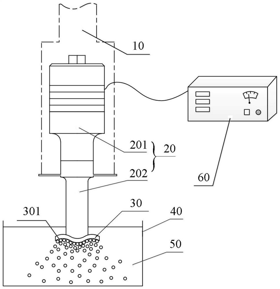
[0026] Such as figure 1 As shown, the ultrasonic cavitation shot peening method provided in this embodiment includes:

[0027] An ultrasonic assembly 20 is provided, the ultrasonic assembly 20 includes an ultrasonic transducer 201 and an ultrasonic horn 202 connected to the ultrasonic transducer;

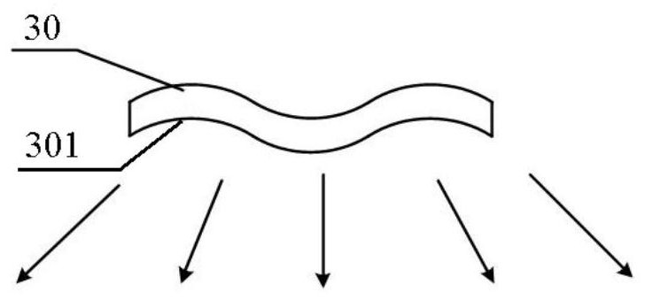
[0028] A first workpiece 30 is provided, the first workpiece 30 includes a first surface to be treated 301, the first workpiece 30 is detachably connected to the ultrasonic horn 202 and exposes the first surface to be treated 301;

[0029] The ultrasonic component 20 is communicated with the ultrasonic power supply 60, and the first surface to be treated 301 is immersed in the liquid medium 50, so that the ultrasonic waves generated by the ultrasonic component 20 are transmitted through the first surface to be treated 301 into the liquid medium 50, the cavitation bubbles in the liquid medium 50 are collapsed to produce micro jets and shock waves to act on the first surface to be tr...

Embodiment 2

[0045] Such as Figure 4 As shown, on the basis of Embodiment 1, this embodiment further includes providing an acoustic wave reflector 70, the acoustic wave reflector 70 includes an acoustic wave reflective surface 701, and the acoustic wave reflector 70 is placed in the liquid medium 50 .

[0046] Specifically, the sound wave reflecting surface 701 is set facing the first surface to be treated 301 . The first surface to be treated 301 radiates high-intensity ultrasonic waves, which are transmitted to the acoustic wave reflecting surface 701 through the liquid medium 50, and the ultrasonic waves are reflected to the first surface to be treated 301 through the acoustic wave reflecting surface 701, so that the first surface to be treated 301 The intensity of ultrasonic waves is further enhanced, thereby improving the ultrasonic cavitation effect of the first surface to be treated 301, enhancing the intensity of ultrasonic cavitation shot peening, and obtaining a surface with ex...


PUM

PropertyMeasurementUnit
hardnessaaaaaaaaaa

Abstract

The present invention relates to an ultrasonic cavitation shot peening method and its use device. The ultrasonic cavitation shot peening method includes: providing an ultrasonic component, the ultrasonic component includes an ultrasonic transducer and an ultrasonic transducer connected to the ultrasonic transducer. Horn; provide a first workpiece, the first workpiece includes a first surface to be treated, the first workpiece is detachably connected to the ultrasonic horn and exposes the first surface to be treated; the The ultrasonic component is communicated with the ultrasonic power supply, and the first surface to be treated is immersed in the liquid medium, so that the ultrasonic waves generated by the ultrasonic component pass into the liquid medium through the first surface to be treated, so that The collapse of cavitation bubbles in the liquid medium generates micro jets and shock waves to achieve shot peening of the first surface to be treated. The method makes the shot-peened surface of the workpiece the surface with the largest sound intensity, reduces the limitation of the shot-peening technology on the surface shape of the workpiece, and expands the processing range.

Description

technical field [0001] The invention relates to the field of metal surface shot peening, in particular to an ultrasonic cavitation shot peening method and a device for use thereof. Background technique [0002] Surface shot peening is a common metal surface strengthening technology, which is widely used to improve the surface hardness, fatigue resistance and corrosion resistance of metal materials. However, the traditional shot peening technology generally impacts the metal surface with shot material at high speed and produces surface plastic deformation, improves the structure of the metal surface layer, implants beneficial residual compressive stress, and then achieves the purpose of surface strengthening. This method is limited by the size of the shot blasting material, and it is difficult to achieve surface strengthening of parts with small sizes, fine tips and complex curved surfaces. The ultrasonic impact strengthening technology uses the shock waves and micro jets ge...

Claims


Application Information

Patent Timeline
Patent Type & Authority Patents(China)
IPC IPC(8): C21D7/06
CPCC21D7/06
Inventor 张庆龙于磊赵夙周瑜婷
Owner NINGBO INST OF MATERIALS TECH & ENG CHINESE ACADEMY OF SCI
Why Eureka
Try Eureka