Micro-buckle battery and preparation method thereof

A button battery and cell technology, applied in the field of micro button battery and its preparation, can solve problems such as damage, easy stretching and cracking, battery leakage, etc., and achieve the effects of improving energy density, uniform stretching, and optimizing chamfering angle.

Pending Publication Date: 2020-01-31
东莞维科电池有限公司
View PDF1 Cites 6 Cited by
  • Summary
  • Abstract
  • Description
  • Claims
  • Application Information

AI Technical Summary

Problems solved by technology

However, the aluminum-plastic film button battery obtained by the method is easily stretched and cracked during use, causing battery leakage or damage

Method used


Image

  • Micro-buckle battery and preparation method thereof
  • Micro-buckle battery and preparation method thereof
  • Micro-buckle battery and preparation method thereof

Examples


Embodiment 1

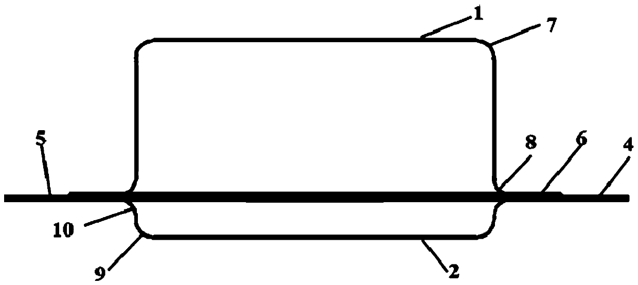
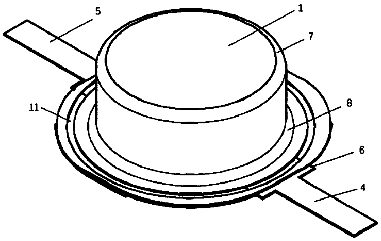
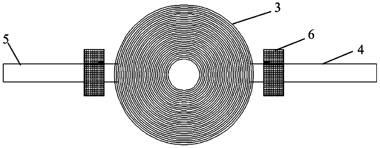
[0062] This embodiment provides a kind of micro-button battery, and its structural diagram is shown in Figure 1-Figure 4 , the micro-button battery includes a soft-coated casing and an electric core 3 of a winding structure placed in the soft-coated casing, and the soft-coated casing is divided into an upper casing 1 and a lower casing 2 with pits , the upper shell 1 and the lower shell 2 are combined to form a hollow cavity, and the battery core 3 is placed in the cavity; a pit with a radius of R1 is formed between the side wall of the pit in the upper shell 1 and the top layer of the pit. The first outer chamfer 7; the edge of the mouth of the pit in the upper shell 1 forms a first inner chamfer 8 with a radius of R2; the pit side wall and the top layer in the lower shell 2 form a radius of R3 The second outer chamfer 9; the edge of the mouth of the pit in the lower shell 2 forms a second inner chamfer 10 with a radius of R4; A circle of encapsulation area 11 of the core; ...

Embodiment 2

[0072] The difference from Example 1 is that the punched pit depth (pit depth) of the upper shell 1 is 4.4 mm, the gap size of the concave and convex dies is 0.25 mm, the maximum diameter of the pit is 12 mm, and the first outer chamfer is 7 mm. The radius R1 of the first chamfer 8 is 1.95mm, and the radius R2 of the first inner chamfer 8 is 0.6mm;

[0073] The depth of the punched pit of the lower shell 2 is 1.0mm, the gap size of the concave and convex die is 0.25mm, the maximum diameter of the pit is 12mm, the radius R3 of the second outer chamfer 9 is 0.25mm, and the radius of the second inner chamfer 10 R4 is 0.6mm.

Embodiment 3

[0075] The difference from Example 1 is that the depth of the punched pit (pit depth) of the upper shell 1 is 6mm, the gap size of the concave and convex dies is 0.30mm, the maximum diameter of the pit is 12mm, and the first outer chamfer 7 The radius R1 is 2.75mm, and the radius R2 of the first inner chamfer 8 is 0.8mm;

[0076] The depth of the punched pit of the lower shell 2 is 4mm, the gap size of the concave and convex die is 0.25mm, the maximum diameter of the pit is 12mm, the radius R3 of the second outer chamfer 9 is 1.75mm, and the radius R4 of the second inner chamfer 10 is 0.8mm, and the obtained battery model is 1210.


PUM

PropertyMeasurementUnit
Thicknessaaaaaaaaaa
Pit depthaaaaaaaaaa
Pit depthaaaaaaaaaa

Abstract

The invention relates to a micro-buckle battery. The micro-button battery comprises a soft coating shell and a battery core which is arranged in the soft coating shell and has a winding structure, wherein the soft coating shell is divided into an upper shell and a lower shell which are provided with pits, arc-shaped outer chamfers are formed between side walls of the pits and top layers of the pits in the upper shell and the lower shell, and inner chamfers are formed on edges of openings of the pits on the upper shell and the lower shell. The micro-button battery is advantaged in that a specially designed punch forming die is adopted for the soft coating film, lead angles (outer chamfer and inner chamfer) of the formed soft coating film are optimized and calculated, so a problem of liquidleakage or damage of the battery caused by tensile cracking of the battery in the forming or using process can be effectively solved; the battery core with a winding type structure is adopted, the soft coating shell is arranged to be of a pit structure, so the effective space in the battery shell can be fully utilized, the volume energy density of the battery is improved, and the energy density ofthe battery is further improved due to the design of the light-weight soft coating shell.

Description

technical field [0001] The invention belongs to the technical field of batteries, and in particular relates to a micro button battery and a preparation method thereof. Background technique [0002] Lithium-ion batteries are widely used in mobile electronic products because of their high energy density, high voltage, small size, and environmental protection. The safety of lithium-ion batteries has always been the focus of people's most attention during use. The built-in micro button batteries of bluetooth and health medical electronic equipment used for personal use generally have the problem of insufficient safety performance. Metal micro button batteries often swell when the internal pressure of the battery is too large, crack and leak, and in severe cases produce a burst. [0003] At present, the safety structure design of the existing metal micro-button battery is only to punch a safety hole on the cover plate. When the internal pressure reaches a certain level, it will ...

Claims


Application Information

Patent Timeline
IPC IPC(8): H01M10/0525H01M2/02H01M10/0587
CPCH01M10/0525H01M10/0587H01M50/109H01M50/116H01M50/124Y02E60/10Y02P70/50
Inventor 高学友杨高光夏小勇刘文博张霞泉贵岭朱坤庆计阳
Owner 东莞维科电池有限公司
Why Eureka
Try Eureka