
A gear polishing equipment with high polishing precision

A gear polishing, high-precision technology, applied in mechanical equipment, welding equipment, metal processing equipment and other directions, can solve the problems of grinding and polishing, high labor intensity, low safety, etc., to improve the stability of processing, reduce labor intensity, The effect of improving machining accuracy

Active Publication Date: 2021-01-19
ZHEJIANG PUJIANG GEAR
View PDF10 Cites 1 Cited by
  • Summary
  • Abstract
  • Description
  • Claims
  • Application Information

AI Technical Summary

Problems solved by technology

In the process of gear reprocessing, the tooth groove needs to be polished. The existing gear grinding and polishing process only needs to drive the gear to rotate intermittently through the motor, and then control the cutting knife to move to the same position regularly through the mechanical arm to polish the tooth groove. However, the process of grinding and polishing with a cutting tool not only wears the surface of the tooth groove of the gear, but also cannot perform good grinding and polishing on some inner corners, and the machining accuracy is low; at the same time, this processing method can only be used for one tooth groove at a time. Grinding and polishing requires manual real-time detection, and after the grinding is completed, the gears need to be removed manually, which is labor-intensive; and during the grinding and polishing process, high-temperature waste and waste liquid are scattered in the grinding and polishing area. around, less security
Therefore, the existing grinding and polishing equipment for gear processing has the problems of low processing accuracy, high labor intensity and poor safety in the process of reuse.

Method used


Image

  • A gear polishing equipment with high polishing precision
  • A gear polishing equipment with high polishing precision
  • A gear polishing equipment with high polishing precision

Examples


Embodiment Construction

[0019] The present invention will be further described below in conjunction with the examples, but not as a basis for limiting the present invention.

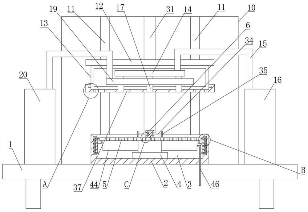
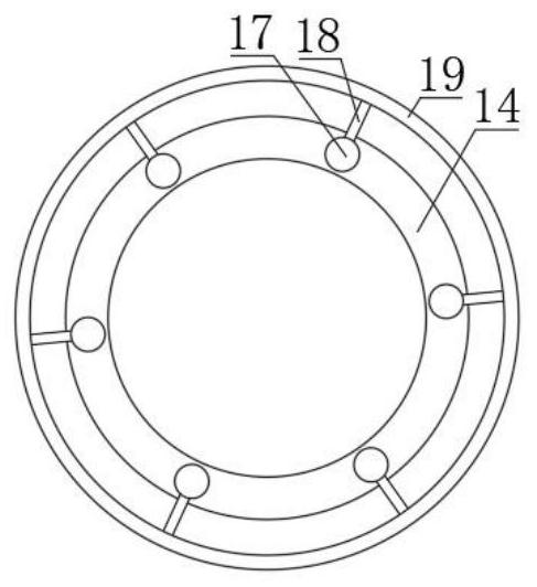
[0020] Example. A gear polishing equipment with high polishing precision, which is composed of Figures 1 to 6 As shown, including a frame 1, a fixed base 2 is arranged on the surface of the frame 1; an adjustment groove 3 is arranged on the fixed base 2, and a hydraulic cylinder 4 is arranged in the adjustment groove 3; a fixed plate 5 is connected to the hydraulic cylinder 4, The middle part of the top surface of the fixed plate 5 is provided with a fixed rod 6, and the fixed rod 6 is provided with two symmetrically distributed automatic stabilizing devices 7; the bottom surface of the fixed plate 5 is provided with a plurality of "L" shaped measuring rods 8, each The measuring rod 8 is connected with a height detection device 9; one side of the fixed base 2 is provided with a lifting seat 10, and the lifting seat 10 is prov...


PUM


Abstract

The invention discloses a gear polishing equipment with high polishing precision, which comprises a frame, and a fixed base is arranged on the frame; an adjustment groove is arranged on the fixed base, and a hydraulic cylinder, a fixed plate, a fixed rod and two hydraulic cylinders are arranged in the adjustment groove. An automatic stabilizing device; a plurality of measuring rods with height detection devices are set on the fixed plate; a lifting seat is set on one side of the fixed base, two electric slide rails and a lifting plate are set on the lifting seat, and a fixed lifting plate is set on the lifting plate. Top seat; the fixed top seat is provided with a ring-shaped main pipe, an air intake pipe, a supercritical carbon dioxide gas supply bottle, a plurality of gas outlet pipes, a plasma tube and a ring-shaped feed pipe, and a plasma gas bottle is connected to the top surface of the ring-shaped feed pipe; fixed A plurality of piezoelectric sensors are arranged on the top seat. The invention can not only improve the processing precision, but also has the advantages of low labor intensity, high work efficiency, wide application range, good processing stability, high safety, convenient use, convenient maintenance, convenient cleaning and long service life.

Description

technical field [0001] The invention relates to a grinding and polishing device for gear processing, in particular to a gear polishing device with high polishing precision. Background technique [0002] A gear is a mechanical element that transmits motion and power through continuous meshing of gear teeth. Due to the smooth transmission of gears, it is widely used in mechanical transmission and the entire mechanical field. In the process of gear reprocessing, the tooth groove needs to be polished. The existing gear grinding and polishing process only needs to drive the gear to rotate intermittently through the motor, and then control the cutting knife to move to the same position regularly through the mechanical arm to polish the tooth groove. However, the process of grinding and polishing with a cutting tool not only wears the surface of the tooth groove of the gear, but also cannot perform good grinding and polishing on some inner corners, and the machining accuracy is low...

Claims


Application Information

Patent Timeline
Patent Type & Authority Patents(China)
IPC IPC(8): B23F19/00B23K10/00C23F4/00
CPCB23F19/00B23K10/003C23F4/00
Inventor 洪新阳黄刚敏郑敏敏周学平张信伟彭翔
Owner ZHEJIANG PUJIANG GEAR
Learn More