Electroplating cavity and manufacturing method
A manufacturing method and cavity technology, applied in the field of ovens, can solve problems such as thermal oxidation and discoloration, poor heat reflection effect, and affect user experience, etc., and achieve good surface heat reflection performance, improved corrosion resistance, and good friction resistance. Effect
- Summary
- Abstract
- Description
- Claims
- Application Information
AI Technical Summary
Problems solved by technology
Method used
Image
Examples
Embodiment 1
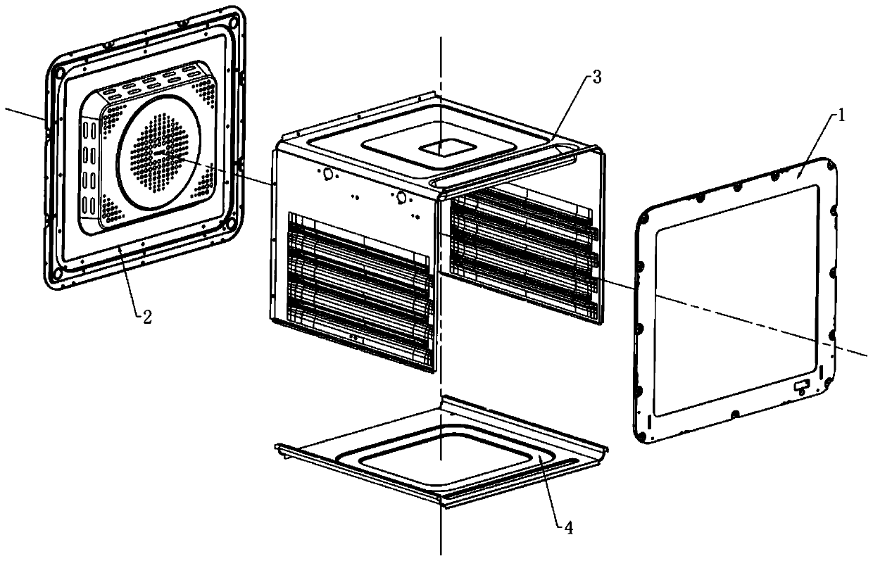
[0048] Such as figure 1 As shown, a kind of electroplating cavity comprises a cavity blank and an electroplating layer coated on the cavity blank. The cavity blank includes a front plate, a rear plate, a U plate, and a bottom plate. In the electroplating layer Each component includes: 70%-90% copper; 10%-20% nickel; 0.5%-5% chromium, more preferably 75%-85% copper; 13%-16% nickel; 2% chromium ~3%.
[0049] Furthermore, it can also be considered in the present invention that the thickness of the electroplating layer is 12-15 μm, more preferably 12-13.5 μm.
Embodiment 2
[0051] A method for manufacturing an electroplating cavity. First, the appearance of the cavity blank is inspected, and the cavity blank that passes the inspection is hung on a hanger; the manufacturing method also includes the following steps:
[0052] Step 1: pre-plating treatment: the pre-plating treatment acts on the surface of the cavity blank to remove the grease layer, wax layer and rust film on the surface of the cavity blank, and improve the bonding force between the electroplating layer and the cavity blank, To increase the efficiency of electroplating.
[0053] Include the following steps:
[0054] A. Place the cavity blank in the degreasing tank for thermal degreasing;
[0055] B. Place the cavity blank processed in the above steps in a washing tank for washing;
[0056] C. Place the cavity blank processed in the above steps in the wax removal tank for ultrasonic wax removal
[0057] D. Place the cavity blank processed in the above steps in a washing tank for wash...
Embodiment 3
[0094] Abrasion test of stainless steel bottom plate
[0095] 1. Test purpose: To investigate the electroplated nickel-chromium layer on the stainless steel bottom plate (the components in the electroplated nickel-chromium layer include: copper 70% to 90%; nickel 10% to 20%; chromium 0.5% to 5%, with a thickness of 12 -15μm) wear resistance.
[0096] 2. Test conditions:
[0097] a. Test product placement: consistent with the actual use conditions
[0098] b. Test environment: Verify on the TOKIT oven, assemble an electroplated stainless steel bottom plate and an unplated stainless steel bottom plate for a comparative test.
[0099] 3. Test method:
[0100]a. Before the aging test of the prototype, check the stainless steel bottom plate. Both the electroplated stainless steel bottom plate and the unplated stainless steel bottom plate are intact without scratches.
[0101] b. Use a scouring pad to wipe back and forth 20cm on the base plate as one cycle, and perform a total o...
PUM
| Property | Measurement | Unit |
|---|---|---|
| thickness | aaaaa | aaaaa |
Abstract
Description
Claims
Application Information
 - R&D
- Intellectual Property
- Life Sciences
- Materials
- Tech Scout
- Unparalleled Data Quality
- Higher Quality Content
- 60% Fewer Hallucinations
Browse by: Latest US Patents, China's latest patents, Technical Efficacy Thesaurus, Application Domain, Technology Topic, Popular Technical Reports.
© 2025 PatSnap. All rights reserved.Legal|Privacy policy|Modern Slavery Act Transparency Statement|Sitemap|About US| Contact US: help@patsnap.com

