A dual-purpose punching machine

A hole punching machine and dual-purpose technology, which is applied in the direction of mechanical equipment, rotary drilling rigs, machines/engines, etc., can solve problems such as easy shaking, complicated and cumbersome cleaning process, and large vibration amplitude, and achieve good stability.

Active Publication Date: 2021-09-17
何同均
View PDF7 Cites 0 Cited by
  • Summary
  • Abstract
  • Description
  • Claims
  • Application Information

AI Technical Summary

Problems solved by technology

[0004] The present invention provides a dual-purpose hole punching machine, which can effectively solve the above-mentioned background technology. The hole punching machines on the market currently have a large vibration amplitude during use, and are prone to shaking during the hole drilling process, resulting in failure or failure of the hole. The hole is skewed. At the same time, the existing hole punching machine can only be used manually or only for the hydraulic arm of the excavator. During the operation of the hole punching machine, more soil particles are easy to accumulate on the top of the hole, which is not conducive to ensuring the hole. The depth of the drilling hole of the machine is also not conducive to the removal of the screw rod and the storage of the hole puncher itself. After the hole is drilled, there will be more floating dust on the surface of the screw rod, and the cleaning process is more complicated and cumbersome.

Method used


Image

  • A dual-purpose punching machine
  • A dual-purpose punching machine
  • A dual-purpose punching machine

Examples


Embodiment Construction

[0029] The preferred embodiments of the present invention will be described below in conjunction with the accompanying drawings. It should be understood that the preferred embodiments described here are only used to illustrate and explain the present invention, and are not intended to limit the present invention.

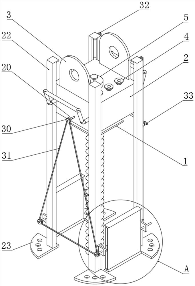
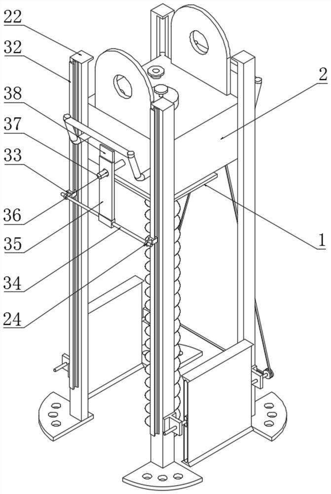
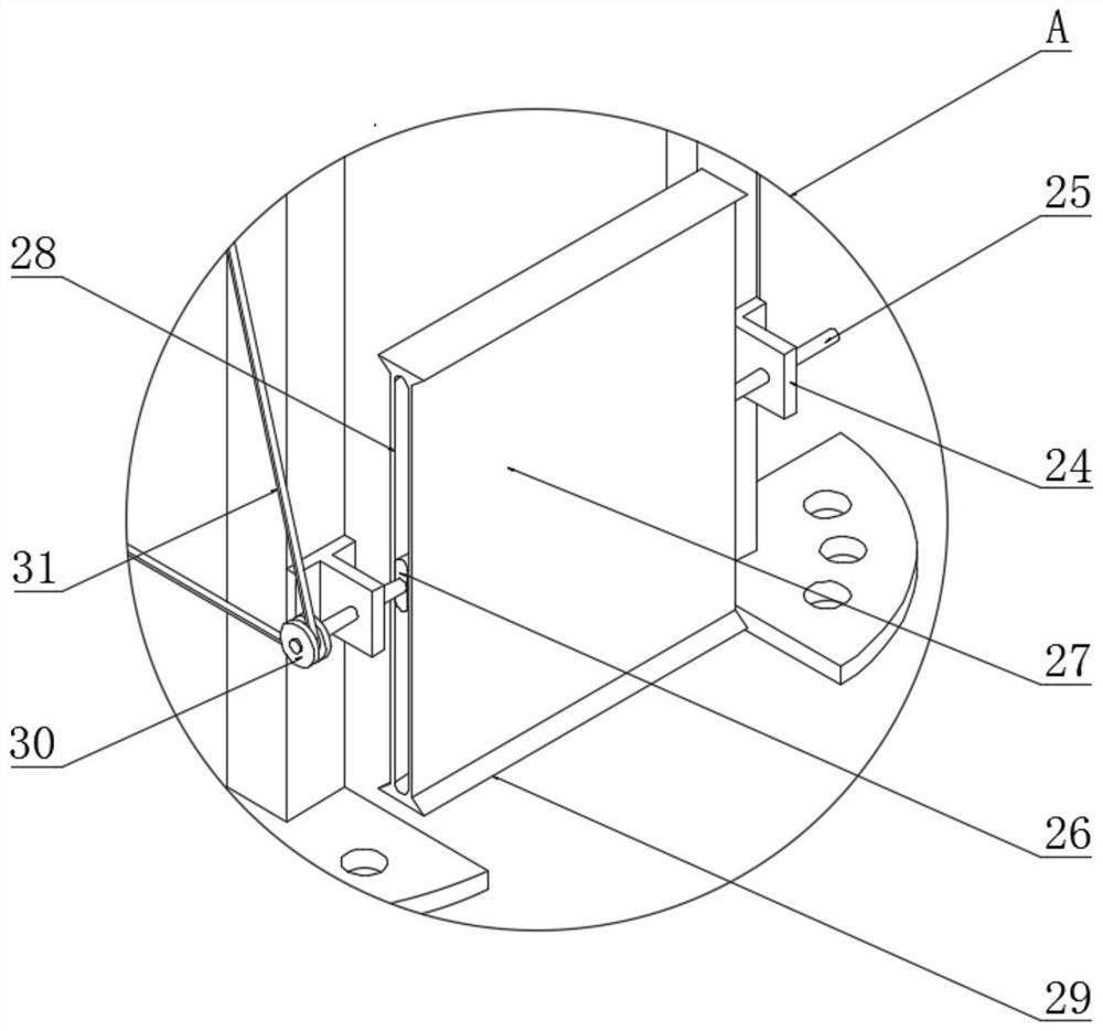
[0030] Example: such as Figure 1-6As shown, the present invention provides a technical solution, a dual-purpose punching machine, including a punching machine body 1, a protective box 2, a mounting piece 3, a mounting flange 4, a lubricating oil tank 5, a screw rod 6, a connecting screw Hole 7, screw block 8, extrusion plate 9, injection pipe 10, gasoline engine 11, hydraulic motor 12, guide pipe 13, driving gear 14, first driven gear 15, screw rod 16, second driven gear 17 , driving bevel gear 18, driven bevel gear 19, driving shaft 20, mounting bump 21, mounting rod 22, fixed bottom plate 23, single clevis mounting part 24, driven shaft 25, flat cylinder 26, scra...


PUM


Abstract

The invention discloses a dual-purpose hole punching machine, which comprises a cleaning plate, a cleaning brush, a scraper, a triangular bump, a mounting rod and a fixed bottom plate, a cleaning brush is installed on the top of the cleaning plate, and both sides of the bottom of the scraper are Triangular bumps are provided, and a fixed bottom plate is welded on the bottom of the installation rod. The structure of the present invention is scientific and reasonable, and it is safe and convenient to use. A cleaning plate and a cleaning brush are provided, which can effectively clean up the floating soil on the surface of the screw rod, so as to ensure that the screw rod The dryness of the rod; the installation rod and the fixed bottom plate are set to ensure the stability of the hole punching machine body and avoid shaking during the hole drilling process; the scraper and triangular bump are set to facilitate the cleaning of the soil on the edge of the hole and avoid digging out The soil returns to the hole; the mounting piece and the hydraulic motor are installed to facilitate installation on the hydraulic arm of the excavator, which can be used manually or mechanically; the lubricating oil tank and the injection pipe are installed to ensure the stable rotation of the internal gear and reduce the Damage to gear teeth.

Description

technical field [0001] The invention relates to the technical field of engineering machinery, in particular to a dual-purpose punching machine. Background technique [0002] In today's earthwork construction projects, road surface construction and maintenance, mobile lifting and unloading operations and various construction projects, the necessary mechanical equipment for comprehensive mechanized construction projects can be called construction machinery. Industrial machinery is a general term for machinery and equipment that uses tools that are harder and sharper than the target to leave cylindrical holes or holes on the target by means of rotary cutting or rotary extrusion, and the earth drill is used as the core of the drilling machine. One, also known as a hole puncher, is used for on-site hole punching and excavation. [0003] At present, the hole punching machines on the market not only have a large vibration amplitude during use, but also tend to shake during the dri...

Claims


Application Information

Patent Timeline
Patent Type & Authority Patents(China)
IPC IPC(8): E21B7/02E21B15/00E21B3/02E21B12/06F02B61/06F16H57/04
CPCE21B3/02E21B7/028E21B12/06E21B15/00F02B61/06F16H57/0434F16H57/0493
Inventor 李艳欣
Owner 何同均
Why Eureka
Try Eureka