
Self-stabilizing steam pressurization system and working method thereof

A pressurized system, self-stabilizing technology, applied in pipeline systems, components of pumping devices for elastic fluids, gas/liquid distribution and storage, etc., can solve noise pollution, low degree of automation, and poor sealing effect of high-pressure steam to avoid misjudgment and liberate the labor force

Pending Publication Date: 2020-02-04
CHONGQING JIANGJIN SHIPBUILDING IND
View PDF0 Cites 2 Cited by
  • Summary
  • Abstract
  • Description
  • Claims
  • Application Information

AI Technical Summary

Problems solved by technology

The conventional pressurization method is a steam ejector, which needs to consume high-pressure steam, and is accompanied by a large amount of capacity loss when the high-pressure steam and low-pressure steam are mixed, resulting in a low energy utilization rate in this method, and due to the steam induced The injector has no moving parts, making operation difficult to adjust and less automated
The other is the Roots-type compressor. Because the Roots-type compressor relies on the tightly controlled gap between the two rotors to achieve sealing, the sealing effect on high-pressure steam is not good, resulting in low efficiency of the whole machine, and the steam outlet There are pressure pulsations and loud noises, which will bring new noise pollution problems

Method used


Image

  • Self-stabilizing steam pressurization system and working method thereof

Examples


Embodiment Construction

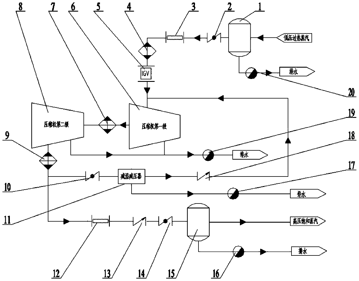
[0033] A self-stabilizing steam pressurization system, the structural principle diagram is as follows figure 1 As shown, the system mainly includes the inlet buffer tank 1, the inlet butterfly valve 2, the inlet bellows 3, the inlet sprinkler 4, the inlet guide vane mechanism 5, the first stage of the compressor 6, and the interstage sprinkler 7 , the second stage of the compressor 8, the exhaust steam sprinkler 9, the anti-breathing regulating valve 10, the temperature and pressure reducer 11, the exhaust bellows 12, the check valve 13, the exhaust butterfly valve 14, the exhaust buffer tank 15, Steam trap 16, steam trap 17, check valve 18, steam trap 19, steam trap 20, etc. Among them, the inlet buffer tank 1 and the exhaust buffer tank 15 are equipped with safety valves, which play the role of safety pressure relief; the inlet butterfly valve 2 and the exhaust butterfly valve 14 are switch-type butterfly valves, which play the role of opening and closing the pipeline. The ...


PUM


Abstract

The invention aims to overcome the defects in the prior art, and provides a self-stabilizing steam pressurization system and a working method thereof. The heat energy recovery rate is high, and the automation degree is high. The self-stabilizing steam pressurization system comprises a steam inlet buffer tank, a steam inlet valve, a steam inlet water sprayer, a steam inlet guide vane mechanism, a compressor first stage, an interstage water sprayer, a compressor second stage, a steam exhaust water sprayer, a check valve, a steam exhaust valve and a steam exhaust buffer tank which are sequentially connected in series through pipelines, wherein the steam inlet buffer tank is used for buffering steam; the steam inlet valve and the steam exhaust valve are used as valves for opening and closing the pipelines of the system; the steam inlet water sprayer, the interstage water sprayer and the steam exhaust water sprayer are used for carrying out mist spraying on superheated steam, and the superheated steam is converted into saturated steam; the compressor first stage and the compressor second stage are used for compressing and pressurizing the input steam; the steam inlet guide vane mechanism is used for controlling the flow of the steam entering the compressor first stage by adjusting the size of a throat between guide vanes; and the steam exhaust buffer tank is used for buffering and outputting the input steam.

Description

technical field [0001] The invention relates to the technical field of energy saving and environmental protection, in particular to a self-stabilizing steam boosting system and a working method thereof. Background technique [0002] With the increasingly serious environmental pollution and the increasingly tense energy resources, energy conservation and environmental protection have become one of the hot topics in the world, especially for major factories and enterprises. Many heat exchange equipment in many smelters, paper mills, and power plants will produce a large amount of waste steam after heat exchange. Due to the low pressure and low grade of these steam, it is difficult to directly recycle them. If the cooling tower is used to condense Recycling waste steam by other methods also consumes energy and has little benefit, so it is often directly discharged into the atmosphere, which will not only cause environmental pollution, but also a huge waste of energy. At presen...

Claims


Application Information

Patent Timeline
IPC IPC(8): F04D17/12F04D29/46F04D27/00F04D27/02F04D29/66F17D1/07F17D1/20F17D5/00
CPCF04D17/12F04D29/462F04D27/002F04D27/008F04D27/0215F04D29/667F17D1/07F17D1/20F17D5/00
Inventor 尹贤军文鑫但光局熊涛李扬邓德见龚由春
Owner CHONGQING JIANGJIN SHIPBUILDING IND
Learn More